1. Hydraulic power steering
1. Hydraulic power steering system overview
The hydraulic power steering system consists of the following components.
- Power steering oil pump
- Reservoir tank
- Power steering unit
- Pressure hose
- Return hose
2. Hydraulic power steering unit
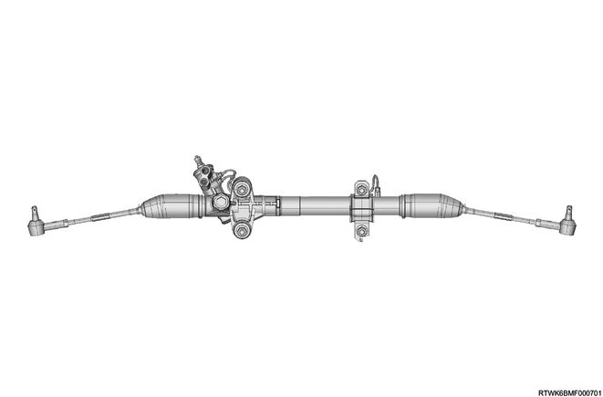
The hydraulic power steering unit is a rack and pinion type.
Adjust the toe-in angle by turning the tie rods on both the left and right side.
The steering housing cannot be disassembled.
3. Power steering oil pump
The power steering oil pump consists of the following components.
- Cam ring
- Side plate
- Rotor
- Vane
- Flow control valve
- Spring
Power steering oil pump (4JJ3 engine models)
Power steering oil pump (RZ4E-TC engine models)
The power steering oil pump is a vane type.
The power steering oil pump has internal components such as the rotor and vane in the housing, and force-feeds the power steering fluid using rotor rotation.
There are 2 ports on the power steering oil pump. The power steering fluid taken in from the suction port is force-fed by the rotor, vane, etc., and is discharged from the outlet port.
The flow control valve is installed to the outlet port of the pump, and the pressure relief valve inside the flow control valve restricts pump pressure.
The power steering oil pumps for 4JJ3 and RZ4E-TC engine cannot be disassembled.
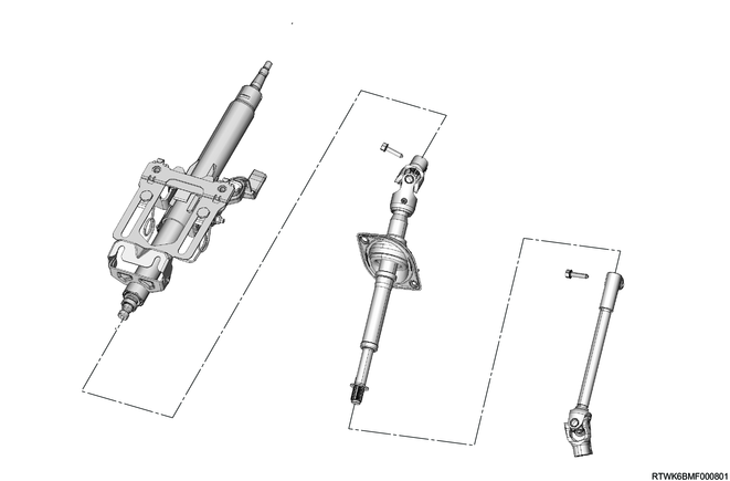
4. Steering column
In addition to the steering function, the steering column has 3 important functions.
1) The steering column is designed to absorb collision energy at the time of forward collision to minimize the possibility the driver being injured.
2) The ignition switch and steering lock are installed to the steering column.
3) The steering lock is equipped with the steering column, and thereby locks the ignition and steering at the same time to prevent vehicle thefts.
The steering column can be disassembled and assembled.
When assembling the steering column, in order to ensure operation of collision energy absorption, make sure to use a genuine fastener and tighten to the specified torque as necessary.
When removing the steering column from the vehicle, take sufficient care handling it. If it strong contact is made with the steering shaft or the shift lever end, or if the steering column assembly is dropping, the fastener that maintains the rigidity of the steering column may shear or become loose.
2. Electric power steering control system overview
1. Overview
The electric power steering control system has a steering assist mechanism which is driven electrically, whereas the previous mechanism is driven hydraulically.
Legend
- Electric power steering unit
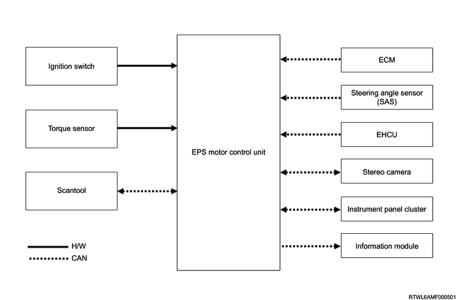
2. Construction
The electric power steering control system consists of the EPS motor control unit, torque sensor, and other ECUs.
Diagram of input/output
3. Functions and controls
The electric power steering control system has the following controls and functions.
- Electric power steering assist control
- Drive assist system cooperative control
- Information function
- Fail-safe function
3. Electric power steering control system
1. Electric power steering assist control
1) Base assist control
The base assist control is a control for reducing the steering force. The base assist control is performed based on the steering force and vehicle speed.
2) Inertia correction control
The inertia correction control is a control for improving response of the base assist control. The inertia correction control is performed based on the steering torque and vehicle speed.
3) Damping correction control
The damping correction control is a control for reducing small vibration transmitted to the steering wheel. The damping correction control is performed based on the motor rotation speed and vehicle speed.
4) Returnability control
The returnability control is a control for improving the steering wheel return to the neutral position. The returnability control is performed based on the steering force, steering angle, steering angular speed, and vehicle speed.
5) Rack end control
The rack end control is a control that protects the electric power steering system by reducing the motor drive current when the steering wheel is turned with the vehicle stopped.
6) Overheat prevention control
The overheat prevention control protects the electric power steering system by reducing the motor drive current in steps when the EPS motor control unit heats up abnormally due to a continual steering with the vehicle stopped, etc.
Note
- If the overheat prevention control is activated, do not operate the steering wheel for a while. The assist function resumes when the temperature decreases.
2. Drive assist system cooperative control
The EPS motor control unit and stereo camera perform the cooperative control of the following functions.
- Lane Departure Prevention (LDP)
- Emergency Lane Keeping (ELK)
- Lane Keep Assist System (LKAS)
Note
- For details of each function, refer to function, structure, operation of stereo camera in driver assistance system.
3. Information function
The EPS motor control unit informs the driver of malfunctions in the electric power steering system via the instrument panel cluster.
4. Fail-safe function
If the EPS motor control unit detects a malfunction in the electric power steering system, the DTC is set. The EPS motor control unit limits or stops the assist control according to the malfunction contents, and stops the drive assist system cooperative control.
4. Electric power steering control system components
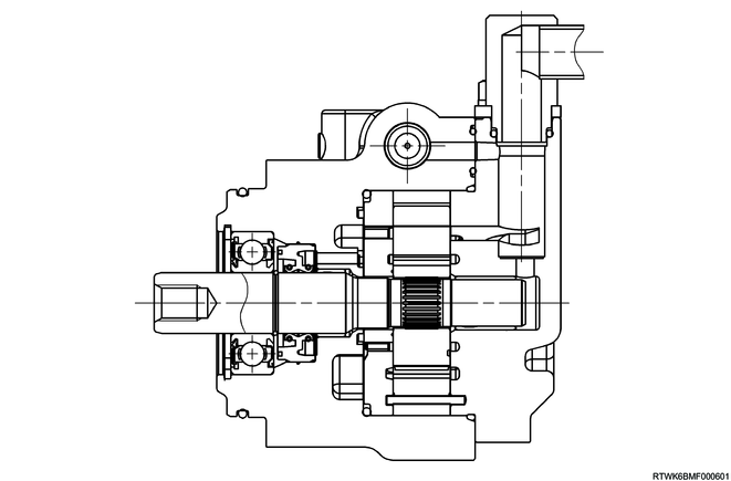
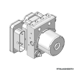
1. Electric power steering unit
The electric power steering unit consists of the rack housing, rack bar, stub shaft, pinion gear, reduction drive, torque sensor, EPS motor control unit, etc., and is installed to the 2nd cross member.

Legend
- Stub shaft
- Torque sensor
- Electric power steering unit
- EPS motor control unit
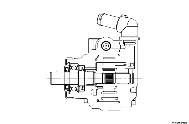
2. EPS motor control unit
The ECU and motor are integrated into the EPS motor control unit which is installed to the electric power steering unit. The EPS motor control unit drives the motor based on the signals from the torque sensor and other ECUs, and assists the driver in steering.

Legend
- EPS motor control unit
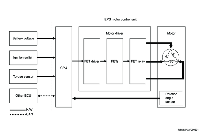
3. Motor
The motor is built into the EPS motor control unit, and steers the tires by driving the rack bar through the reduction drive. The brushless DC motor is adopted, and the motor incorporates a rotation angle sensor. The EPS motor control unit controls the motor based on the rotation angle sensor signals.
Motor control block diagram
4. Torque sensor
1) Overview
The housing, ring core, and Hall IC are integrated into the torque sensor which is installed to the outer circumference of the stub shaft of the electric power steering unit. The torque sensor is a non-contact type sensor that detects the steering force and steering direction of the steering wheel. The torque sensor has 2 sensor parts to ensure safety and reliability. The EPS motor control unit calculates the motor drive current value based on the torque sensor signal.
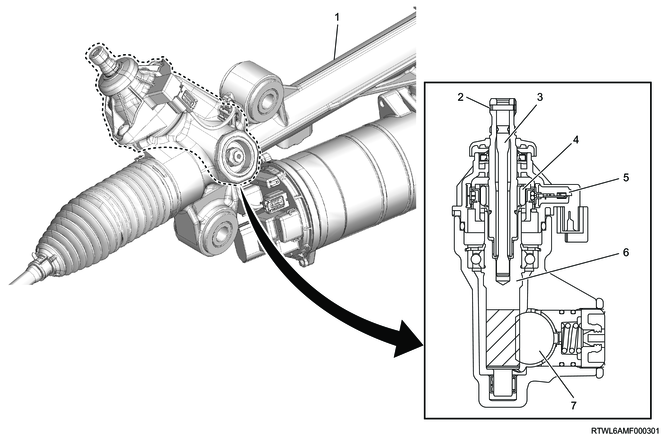
Legend
- Electric power steering unit
- Stub shaft
- Torsion bar
- Magnet
- Torque sensor
- Pinion shaft (Steering wheel side)
- Rack bar
2) Operation
When the steering wheel is steered, a relative angle difference generates between the magnet installed to the stub shaft and the yoke installed to the pinion shaft, because the stub shaft and pinion shaft are mechanically connected via the torsion bar. When a relative angle difference generates between the magnet and the yoke, a magnetic flux change is transmitted to the Hall IC via the ring core. By sensing the change in magnetic flux, the Hall IC can indirectly detect the steering force and steering direction of the steering wheel.
5. ECM
The ECM transmits the engine speed and vehicle speed information to the EPS motor control unit via the CAN communication circuit. The EPS motor control unit controls the electric power steering control system based on the information transmitted from the ECM.
6. Stereo camera
The stereo camera transmits a steering request and the operating information of the drive assist system to the EPS motor control unit via the CAN communication circuit. The EPS motor control unit controls the electric power steering control system based on the information transmitted from the stereo camera.
7. EHCU
The EHCU transmits information of the wheel speed, acceleration in the forward, rearward, left, and right directions, and yaw rate to the EPS motor control unit. The EPS motor control unit controls the electric power steering control system based on the information transmitted from the EHCU.
8. Steering angle sensor
The steering angle sensor transmits the steering angle information of the steering wheel to the EPS motor control unit via the CAN communication circuit. The EPS motor control unit controls the electric power steering control system based on the information transmitted from the steering angle sensor.

Legend
- Steering angle sensor
- Combination switch
9. Information module
The information module is installed to the driver-side dash side panel. The EPS motor control unit transmits the control information and diagnostic information to the information module via the CAN communication circuit.
10. Steering system failure warning light
The steering system failure warning light informs the driver of malfunctions in the electric power steering control system. The EPS motor control unit requests the instrument panel cluster to illuminate the steering system failure warning light via the CAN communication circuit.

11. Master warning light
The master warning light illuminates when the related system malfunctions.
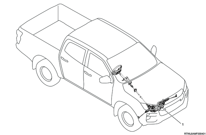
5. Electric power steering control system component views
Legend
- Electric power steering unit
Legend
- Stub shaft
- Torque sensor
- Electric power steering unit
- EPS motor control unit
6. General circuit diagram
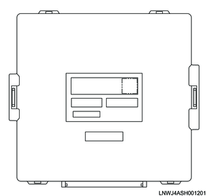
1. EPS motor control unit general circuit diagram
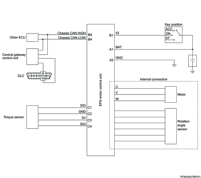
2. EPS motor control unit outline view and connector face

3. EPS motor control unit pin layout
| PIN No. |
Pin function |
| 1 |
Battery voltage |
| 2 |
Ground |
| PIN No. |
Pin function |
| 1 |
Ignition voltage |
| 2 |
- |
| 3 |
- |
| 4 |
Chassis CAN (Low) |
| 5 |
Chassis CAN (High) |
| 6 |
- |
| PIN No. |
Pin function |
| 1 |
Torque sensor signal (TSS) |
| 2 |
Torque sensor low reference (TSG) |
| 3 |
Torque sensor 5 volts reference (TSV) |
| 4 |
Torque sensor signal (TSM) |