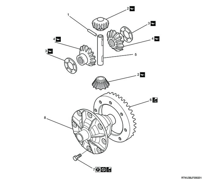
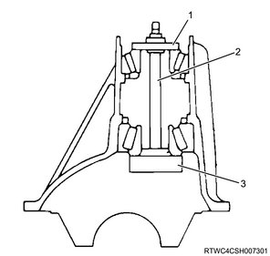
1. Component views
Front differential cage (φ194 mm {7.64 in})
Part name
- Lock pin
- Pinion gear
- Side gear thrust washer
- Side gear
- Cross pin
- Ring gear
- Bolt
- Differential cage
Tightening torque
7: 108 N・m { 11.0 kgf・m / 80 lb・ft }
2. Final drive safety information
When assembling, if nothing in particular is specified, refer to the following and apply or add differential oil.
Refer to "201.General Information 14B.Vehicle Information recommended fluids, lubricants and diesel fuels".
3. Differential cage reassembly
1) Apply differential oil to the following parts.
- Side gear
- Pinion gear
- Side gear thrust washer
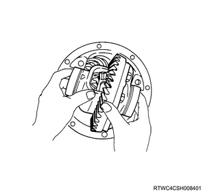
2) Install the side gear and side gear thrust washer to the differential cage.
3) Install the pinion gear to the differential cage.
Note
- While turning the 2 pinion gears in the same direction, engage them with the side gear and install the pinion gears.
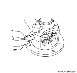
4) Install the cross pin to the differential cage.
Note
- Align the lock pin holes of the cross pin and differential cage, and install the cross pin.
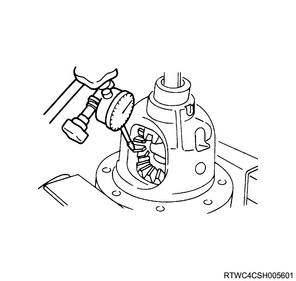
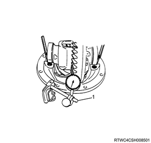
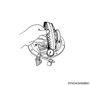
5) Measure the backlash of the side gear and pinion gear using a dial gauge.
Caution
- If the backlash is outside the specified range, change the side gear thrust washer thickness and adjust.
Standard: 0.10 to 0.20 mm { 0.004 to 0.008 in }
| Thrust washer thicknesses |
| 1.00 mm { 0.039 in } |
| 1.05 mm { 0.041 in } |
| 1.10 mm { 0.043 in } |
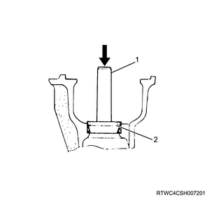
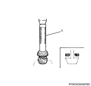
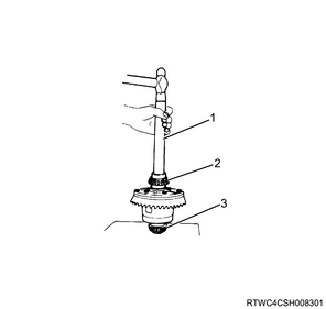
6) Install the lock pin to the differential cage.
7) Stake the lock pin.
Caution
- Securely stake the lock pin so that it does not come out.
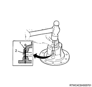
Legend
- Staked section
- Lock pin
8) Apply LOCTITE 263 to the threaded portion of the bolts and the ring gear threaded holes.
9) Install the ring gear to the differential cage.
Note
- Apply LOCTITE 263 to the threaded portion of the bolts from the end toward the center in a straight line.
Caution
- If using any adhesive other than LOCTITE 263, the bolts may be loosened or broken.
- Do not reuse the bolts, when replacing the ring gear.
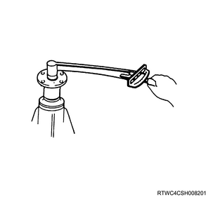
Ring gear bolt tightening order
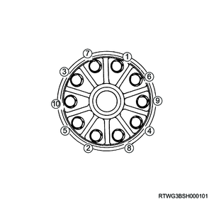
Tightening torque: 108 N・m { 11.0 kgf・m / 80 lb・ft }
4. Final drive reassembly
1) Install the outer bearing outer race to the differential carrier using the special tool.
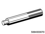
SST: 5-8840-0007-0 - grip
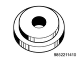
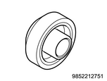
SST: 9-8522-1141-0 - bearing installer
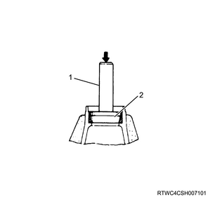
Legend
- 5-8840-0007-0
- 9-8522-1141-0
2) Install the inner bearing outer race to the differential carrier using the special tool.
SST: 5-8840-0007-0 - grip
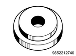
SST: 9-8522-1274-0 - bearing installer
Legend
- 5-8840-0007-0
- 9-8522-1274-0
3) Apply differential oil to the inner bearing inner race and outer bearing inner race.
4) Install the following parts to the differential carrier.
- Inner bearing inner race
- Outer bearing inner race
- Special tool
Caution
- Thoroughly clean the special tool before using it.
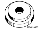
SST: 5-8840-2085-0 - pilot
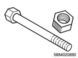
SST: 5-8840-2089-0 - stud & nut
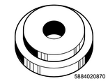
SST: 5-8840-2087-0 - gauge plate
Legend
- 5-8840-2085-0
- 5-8840-2089-0
- 5-8840-2087-0
5) Tighten the special tool nut.
6) Clean the side bearing installation section.
Tightening torque: 2.3 N・m { 0.23 kgf・m / 20 lb・in }
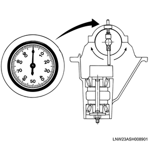
7) Install the special tool to the differential carrier.
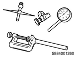
SST: 5-8840-0126-0 - dial indicator

SST: 5-8840-2088-0 - disc
SST: 5-8840-0128-0 - arbor
SST: 5-8840-2087-0 - gauge plate
8) Install the bearing cap to the differential carrier.
Tightening torque: 98 N・m { 10.0 kgf・m / 72 lb・ft }

Legend
- 5-8840-0126-0
- 5-8840-2088-0
- 5-8840-0128-0
- 5-8840-2087-0
Note
- The dial indicator scale display is in inches.
9) Set the dial indicator scale to 0.
10) Bring the dial indicator into contact with the arbor plunger section, push the dial indicator down to the point where the needle rotates approximately halfway in the clockwise direction, and secure.
11) Set the dial indicator scale to 0.
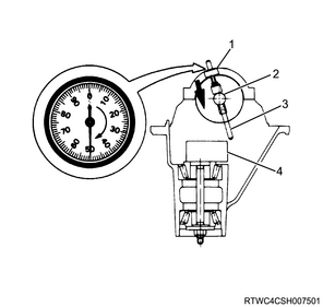
Legend
- 5-8840-0126-0
- 5-8840-0128-0
- Plunger (5-8840-0128-0)
- 5-8840-2087-0
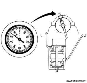
12) Place the end of the arbor plunger on top of the gauge plate.
13) Gently move the arbor back and forth, and verify the position where the dial indicator runout is largest.
14) Set the dial indicator scale to 0 at the position where the dial indicator runout is largest.
15) Using the same procedure, make sure the scale reads 0.
16) Rotate the arbor and move the end of the plunger away from the gauge plate.
17) Record the value indicated on the dial indicator.
Note
- This value is the shim thickness.
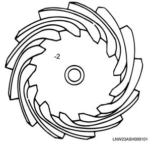
18) Record the pinion depth code on the drive pinion head section.
If the value is positive, the mesh depth is too large, so decrease the shim.
If the value is negative, the mesh depth is too small, so increase the shim.
Ex: If the value is +2, the mesh depth is 0.02 mm {0.0008 in} too large, so decrease the shim thickness by 0.02 mm {0.0008 in}. If the value is negative, perform the opposite.
19) Select the appropriate adjust shim based on the value read by the dial indicator and the drive pinion code.
Note
- There are 20 types of adjust shims, with thickness ranging from 2.18 mm {0.0858 in} to 2.56 mm {0.1008 in} in 0.02 mm {0.0008 in} increments.
| Dial indicator reading (in) |
Drive pinion depth code |
|||||
| 10 |
8 |
6 |
4 |
2 |
0 |
|
| 0.081 |
||||||
| 0.082 |
||||||
| 0.083 |
||||||
| 0.084 |
||||||
| 0.085 |
||||||
| 0.086 |
2.18 {0.0858} |
|||||
| 0.087 |
2.18 {0.0858} |
2.20 {0.0866} |
||||
| 0.088 |
2.18 {0.0858} |
2.20 {0.0866} |
2.24 {0.0882} |
|||
| 0.089 |
2.18 {0.0858} |
2.20 {0.0866} |
2.24 {0.0882} |
2.26 {0.0890} |
||
| 0.090 |
2.18 {0.0858} |
2.20 {0.0866} |
2.24 {0.0882} |
2.26 {0.0890} |
2.28 {0.0898} |
|
| 0.091 |
2.18 {0.0858} |
2.20 {0.0866} |
2.24 {0.0882} |
2.26 {0.0890} |
2.28 {0.0898} |
2.32 {0.0913} |
| 0.092 |
2.20 {0.0866} |
2.24 {0.0882} |
2.26 {0.0890} |
2.28 {0.0898} |
2.32 {0.0913} |
2.34 {0.0921} |
| 0.093 |
2.24 {0.0882} |
2.26 {0.0890} |
2.28 {0.0898} |
2.32 {0.0913} |
2.34 {0.0921} |
2.36 {0.0929} |
| 0.094 |
2.26 {0.0890} |
2.28 {0.0898} |
2.32 {0.0913} |
2.34 {0.0921} |
2.36 {0.0929} |
2.38 {0.0937} |
| 0.095 |
2.28 {0.0898} |
2.32 {0.0913} |
2.34 {0.0921} |
2.36 {0.0929} |
2.38 {0.0937} |
2.42 {0.0953} |
| 0.096 |
2.32 {0.0913} |
2.34 {0.0921} |
2.36 {0.0929} |
2.38 {0.0937} |
2.42 {0.0953} |
2.44 {0.0961} |
| 0.097 |
2.34 {0.0921} |
2.36 {0.0929} |
2.38 {0.0937} |
2.42 {0.0953} |
2.44 {0.0961} |
2.46 {0.0969} |
| 0.098 |
2.36 {0.0929} |
2.38 {0.0937} |
2.42 {0.0953} |
2.44 {0.0961} |
2.46 {0.0969} |
2.48 {0.0976} |
| 0.099 |
2.38 {0.0937} |
2.42 {0.0953} |
2.44 {0.0961} |
2.46 {0.0969} |
2.48 {0.0976} |
2.52 {0.0992} |
| 0 |
2.42 {0.0953} |
2.44 {0.0961} |
2.46 {0.0969} |
2.48 {0.0976} |
2.52 {0.0992} |
2.54 {0.1000} |
| 0.001 |
2.44 {0.0961} |
2.46 {0.0969} |
2.48 {0.0976} |
2.52 {0.0992} |
2.54 {0.1000} |
2.56 {0.1008} |
| 0.002 |
2.46 {0.0969} |
2.48 {0.0976} |
2.52 {0.0992} |
2.54 {0.1000} |
2.56 {0.1008} |
|
| 0.003 |
2.48 {0.0976} |
2.52 {0.0992} |
2.54 {0.1000} |
2.56 {0.1008} |
||
| 0.004 |
2.52 {0.0992} |
2.54 {0.1000} |
2.56 {0.1008} |
|||
| 0.005 |
2.54 {0.1000} |
2.56 {0.1008} |
||||
| 0.006 |
2.56 {0.1008} |
|||||
| Dial indicator reading (in) |
Drive pinion depth code |
|||||
| 0 |
-2 |
-4 |
-6 |
-8 |
-10 |
|
| 0.081 |
2.18 {0.0858} |
|||||
| 0.082 |
2.18 {0.0858} |
2.20 {0.0866} |
||||
| 0.083 |
2.18 {0.0858} |
2.20 {0.0866} |
2.24 {0.0882} |
|||
| 0.084 |
2.18 {0.0858} |
2.20 {0.0866} |
2.24 {0.0882} |
2.26 {0.0890} |
||
| 0.085 |
2.18 {0.0858} |
2.20 {0.0866} |
2.24 {0.0882} |
2.26 {0.0890} |
2.28 {0.0898} |
|
| 0.086 |
2.18 {0.0858} |
2.20 {0.0866} |
2.24 {0.0882} |
2.26 {0.0890} |
2.28 {0.0898} |
2.32 {0.0913} |
| 0.087 |
2.20 {0.0866} |
2.24 {0.0882} |
2.26 {0.0890} |
2.28 {0.0898} |
2.32 {0.0913} |
2.34 {0.0921} |
| 0.088 |
2.24 {0.0882} |
2.26 {0.0890} |
2.28 {0.0898} |
2.32 {0.0913} |
2.34 {0.0921} |
2.36 {0.0929} |
| 0.089 |
2.26 {0.0890} |
2.28 {0.0898} |
2.32 {0.0913} |
2.34 {0.0921} |
2.36 {0.0929} |
2.38 {0.0937} |
| 0.090 |
2.28 {0.0898} |
2.32 {0.0913} |
2.34 {0.0921} |
2.36 {0.0929} |
2.38 {0.0937} |
2.42 {0.0953} |
| 0.091 |
2.32 {0.0913} |
2.34 {0.0921} |
2.36 {0.0929} |
2.38 {0.0937} |
2.42 {0.0953} |
2.44 {0.0961} |
| 0.092 |
2.34 {0.0921} |
2.36 {0.0929} |
2.38 {0.0937} |
2.42 {0.0953} |
2.44 {0.0961} |
2.46 {0.0969} |
| 0.093 |
2.36 {0.0929} |
2.38 {0.0937} |
2.42 {0.0953} |
2.44 {0.0961} |
2.46 {0.0969} |
2.48 {0.0976} |
| 0.094 |
2.38 {0.0937} |
2.42 {0.0953} |
2.44 {0.0961} |
2.46 {0.0969} |
2.48 {0.0976} |
2.52 {0.0992} |
| 0.095 |
2.42 {0.0953} |
2.44 {0.0961} |
2.46 {0.0969} |
2.48 {0.0976} |
2.52 {0.0992} |
2.54 {0.1000} |
| 0.096 |
2.44 {0.0961} |
2.46 {0.0969} |
2.48 {0.0976} |
2.52 {0.0992} |
2.54 {0.1000} |
2.56 {0.1008} |
| 0.097 |
2.46 {0.0969} |
2.48 {0.0976} |
2.52 {0.0992} |
2.54 {0.1000} |
2.56 {0.1008} |
|
| 0.098 |
2.48 {0.0976} |
2.52 {0.0992} |
2.54 {0.1000} |
2.56 {0.1008} |
||
| 0.099 |
2.52 {0.0992} |
2.54 {0.1000} |
2.56 {0.1008} |
|||
| 0 |
2.54 {0.1000} |
2.56 {0.1008} |
||||
| 0.001 |
2.56 {0.1008} |
|||||
| 0.002 |
||||||
| 0.003 |
||||||
| 0.004 |
||||||
| 0.005 |
||||||
| 0.006 |
||||||
20) Remove the special tool from the differential carrier.
21) Install the adjust shim to the drive pinion.
Note
- Face the chamfered side of the adjust shim toward the pinion head to install.
22) Install the inner bearing inner race to the drive pinion using the special tool and press.
Caution
- Increase the pressure only on the inner bearing inner race.
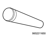
SST: 9-8522-1165-0 - pinion bearing installer
Legend
- 9-8522-1165-0
23) Install the collapsible distance piece and outer bearing inner race to the drive pinion.
Caution
- Do not reuse the collapsible distance piece.
If a collapsible distance piece is reused, the proper preload may not be achieved, and the flange nut may loosen.
24) Install the drive pinion to the differential carrier.
25) Apply differential oil to the lip section of the oil seal.
Caution
- Do not reuse the oil seal.
26) Install the oil seal to the differential carrier using the special tool.

SST: 5-8840-2244-0 - bearing installer
SST: 9-8522-1275-1 - oil seal installer
Caution
- Take care not to mix up with the rear differential carrier oil seal.
- Do not press-fit the oil seal at an angle.
Press-fitting the oil seal at an angle is a cause of oil leakage.

Legend
- 5-8840-2244-0
- 9-8522-1275-1
27) Install the dust cover to the drive pinion.
28) Apply differential oil to the threaded portion of the drive pinion.
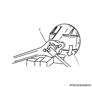
29) Install the flange to the drive pinion using the special tool.
Caution
- Do not reuse the flange nut.
Tightening torque: 177 to 275 N・m { 18.0 to 28.0 kgf・m / 131 to 203 lb・ft }
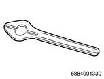
SST: 5-8840-0133-0(J-8614-11) - flange holder
Legend
- 5-8840-0133-0
30) Measure the pinion bearing preload.
Caution
- If the pinion bearing preload is outside the specified range, adjust by further tightening or loosening the flange nut.
Standard: 64 to 113 N・m { 6.5 to 11.5 kgf・m / 47 to 83 lb・ft } New bearing
Standard: 32 to 56 N・m { 3.3 to 5.7 kgf・m / 24 to 41 lb・ft } Reused bearing
31) Install the side bearing inner race to the differential cage using the special tool.
Caution
- Do not install the shim at this stage.
- Use 9-8521-1743-0 as shown in the following diagram, and take care not to damage the opposite inner race.
SST: 9-8522-1164-0 - side bearing installer
SST: 5-8840-0007-0 - grip
SST: 9-8521-1743-0 - adapter
Legend
- 5-8840-0007-0
- 9-8522-1164-0
- 9-8521-1743-0
32) Install the side bearing outer race to the differential cage.
33) Install the differential cage to the differential carrier.
34) Insert the 2 feeler gauges so that the backlash between the outer races of the left and right side bearings and the differential carrier is 0.
Note
- Securely insert the feeler gauge all the way to the bottom of the bearing.
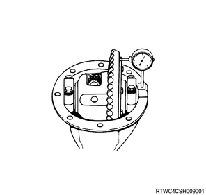
35) Install the special tool to the differential carrier.
Note
- Install the special tool so that it makes contact perpendicularly with the gear teeth of the ring gear.
Legend
- 5-8840-0126-0
36) Change the left and right feeler gauge thicknesses and adjust the backlash.
Standard: 0.13 to 0.18 mm { 0.005 to 0.007 in }
Note
- The dial indicator scale display is in inches.
37) Select a shim based on the thickness of the feeler gauge.
Note
- Select a shim 0.05 mm {0.002 in} thicker than the feeler gauge.
Caution
- Do not reuse the shim.
38) Remove the differential cage from the differential carrier.
39) Remove the side bearing outer race from the differential cage.
Caution
- Organize the removed side bearings according to left/right installation positions and bearing race combinations by using labels, etc.
40) Remove the side bearing inner race from the differential cage using the special tool.
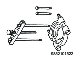
SST: 9-8521-0152-2 - bearing remover
SST: 5-8840-2863-0 - driver tool set
41) Install the shim and side bearing inner race to the differential cage using the special tool.
Note
- Use 9-8521-1743-0 as shown in the following diagram, and take care not to damage the opposite inner race.
SST: 9-8522-1164-0 - side bearing installer
SST: 5-8840-0007-0 - grip
SST: 9-8521-1743-0 - adapter
Legend
- 5-8840-0007-0
- 9-8522-1164-0
- 9-8521-1743-0
42) Install the side bearing outer race to the differential cage.
43) Install the differential cage to the differential carrier.
44) Install the bearing cap to the differential carrier.
Note
- Install according to the alignment marks applied during disassembly.
Tightening torque: 98 N・m { 10.0 kgf・m / 72 lb・ft }
Legend
- Alignment mark
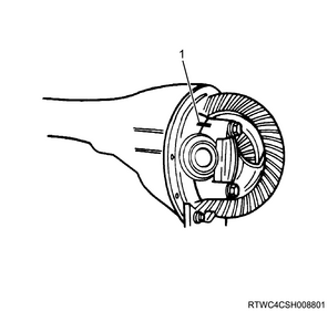
45) Place the dial gauge on the rear surface of the ring gear.
46) Gently turn the ring gear and measure the ring gear runout.
Standard: 0.020 mm { 0.001 in }
Limit: 0.050 mm { 0.002 in }
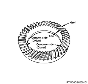
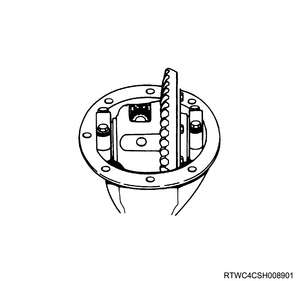
47) Apply red lead primer to the gear teeth of the ring gear.
Note
- Apply to both surfaces of the 7 to 8 gear teeth of the ring gear.
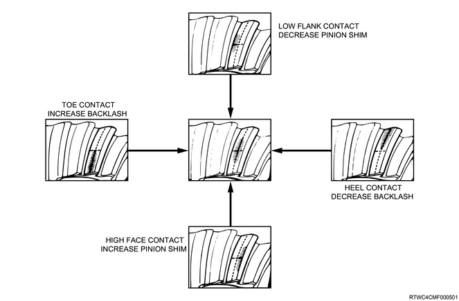
48) Gently rotate the drive pinion forward and backward and inspect the tooth contact.
Caution
- Refer to the following diagram to adjust the positions of the ring gear and drive pinion if the tooth contact of the ring gear and drive pinion is found to be incorrect as a result of the inspection.