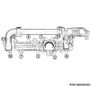
1. Component views
Inlet cover (Except for Euro2 and Euro4 specifications)
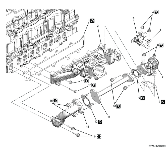
Part name
- Gasket
- Inlet cover
- Relief valve control solenoid valve
- Nut
- Relief valve control solenoid valve bracket
- Nut
- Relief valve
- Gasket
- Gasket
- Bolt
- EGR pipe
- Gasket
- EGR duct
- Bolt
- Bolt
- Bolt
- Nut
Tightening torque
4: 25 N・m { 2.5 kgf・m / 18 lb・ft }
6: 25 N・m { 2.5 kgf・m / 18 lb・ft }
10: 25 N・m { 2.5 kgf・m / 18 lb・ft }
14: 25 N・m { 2.5 kgf・m / 18 lb・ft }
15: 25 N・m { 2.5 kgf・m / 18 lb・ft }
16: 25 N・m { 2.5 kgf・m / 18 lb・ft }
17: 25 N・m { 2.5 kgf・m / 18 lb・ft }
Inlet cover (Euro2 specifications)
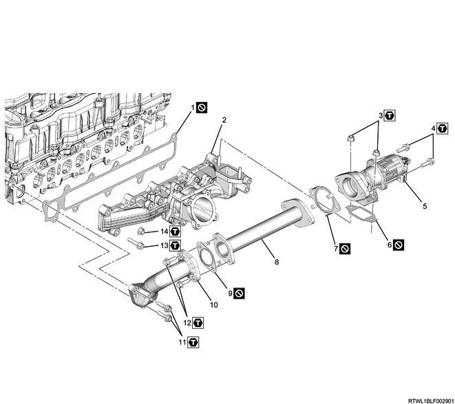
Part name
- Gasket
- Inlet cover
- Nut
- Bolt
- EGR valve
- Gasket
- Gasket
- EGR pipe
- Gasket
- EGR duct
- Bolt
- Bolt
- Bolt
- Nut
Tightening torque
3: 25 N・m { 2.5 kgf・m / 18 lb・ft }
4: 25 N・m { 2.5 kgf・m / 18 lb・ft }
11: 25 N・m { 2.5 kgf・m / 18 lb・ft }
12: 25 N・m { 2.5 kgf・m / 18 lb・ft }
13: 25 N・m { 2.5 kgf・m / 18 lb・ft }
14: 25 N・m { 2.5 kgf・m / 18 lb・ft }
Inlet cover (Euro4 specifications)

Part name
- Gasket
- Inlet cover
- Nut
- Bolt
- EGR valve
- EGR valve gasket
- EGR valve gasket
- EGR cooler
- EGR cooler gasket
- EGR duct
- Bolt
- Bolt
- Bolt
- Nut
- Bolt
Tightening torque
3: 25 N・m { 2.5 kgf・m / 18 lb・ft }
4: 25 N・m { 2.5 kgf・m / 18 lb・ft }
11: 25 N・m { 2.5 kgf・m / 18 lb・ft }
12: 25 N・m { 2.5 kgf・m / 18 lb・ft }
13: 25 N・m { 2.5 kgf・m / 18 lb・ft }
14: 25 N・m { 2.5 kgf・m / 18 lb・ft }
15: 25 N・m { 2.5 kgf・m / 18 lb・ft }
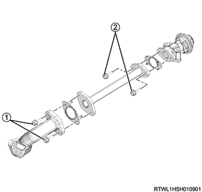
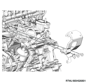
2. EGR installation
1. Euro2 specifications
Caution
- Do not reuse the gasket.
- If the procedures or methods for assembling the EGR device are mistaken, it can lead to cracks in the pipe or gas leaks. Always follow the procedures.
- Even when disassembling only a portion of the EGR-related parts, loosen all the EGR-related parts once, replace the gaskets with new ones, and then temporarily tighten in the following order before performing final tightening.
1) Temporarily tighten the following parts to the EGR pipe in the order shown in the diagram.
- EGR valve
- EGR duct
- Gasket
2) Temporarily tighten the EGR to the inlet cover.
3) Final tighten the following parts to the EGR pipe in the order shown in the diagram.
- EGR valve
- EGR duct
- Gasket
Tightening torque: 25 N・m { 2.5 kgf・m / 18 lb・ft }
4) Final tighten the EGR to the inlet cover.
Tightening torque: 25 N・m { 2.5 kgf・m / 18 lb・ft }
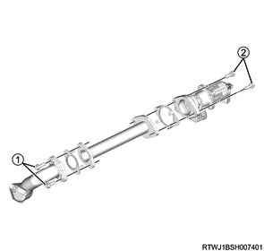
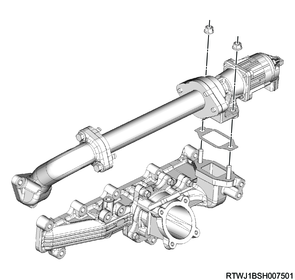
2. Euro4 specifications
Caution
- Do not reuse the gasket.
- If the procedures or methods for assembling the EGR device are mistaken, it can lead to cracks in the pipe or gas leaks. Always follow the procedures.
- Even when disassembling only a portion of the EGR-related parts, loosen all the EGR-related parts once, replace the gaskets with new ones, and then temporarily tighten in the following order before performing final tightening.
1) Temporarily tighten the following parts to the EGR cooler in the order shown in the diagram.
- EGR valve
- EGR duct
- Gasket
2) Temporarily tighten the EGR to the inlet cover in the order shown in the diagram.
3) Final tighten the following parts to the EGR cooler in the order shown in the diagram.
- EGR valve
- EGR duct
- Gasket
Tightening torque: 25 N・m { 2.5 kgf・m / 18 lb・ft }
4) Final tighten the EGR to the inlet cover in the order shown in the diagram.
Tightening torque: 25 N・m { 2.5 kgf・m / 18 lb・ft }
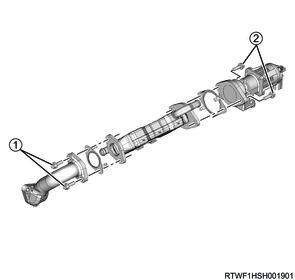
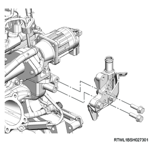
3. Relief valve installation
1. Except for Euro2 and Euro4 specifications
Caution
- Do not reuse the gasket.
1) Temporarily tighten the following parts to the EGR pipe in the order shown in the diagram.
- EGR duct
- Relief valve
- Gasket
2) Temporarily tighten the following parts to the inlet cover in the order shown in the diagram.
- Relief valve
- Relief valve control solenoid valve
- Relief valve control solenoid valve bracket
- Adapter
- Gasket
3) Final tighten the following parts to the EGR pipe in the order shown in the diagram.
- EGR duct
- Relief valve
- Gasket
Tightening torque: 25 N・m { 2.5 kgf・m / 18 lb・ft }
4) Final tighten the following parts to the cylinder head and inlet cover in the order shown in the diagram.
- Relief valve
- Relief valve control solenoid valve
- Relief valve control solenoid valve bracket
- Adapter
- Gasket
Tightening torque: 25 N・m { 2.5 kgf・m / 18 lb・ft }
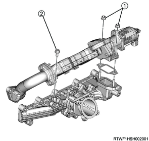
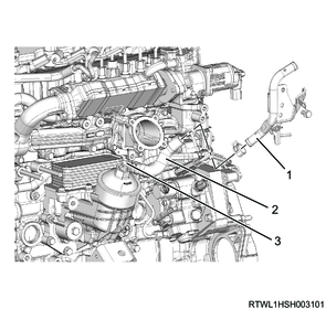
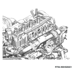
4. Inlet cover installation
1. Except for Euro4 specifications
1) Install the inlet cover and EGR to the cylinder head in the order shown in the diagram.
Tightening torque: 25 N・m { 2.5 kgf・m / 18 lb・ft }
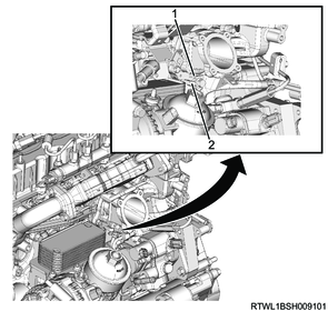
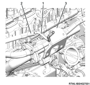
2) Install the harness bracket to the inlet cover.
Note
- Install the harness bracket so that the detent makes full contact with the inlet cover.
Tightening torque: 25 N・m { 2.5 kgf・m / 18 lb・ft }

Legend
- Inlet cover
- Detent
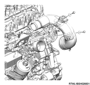
3) Install the air duct bracket to the inlet cover.
Tightening torque: 25 N・m { 2.5 kgf・m / 18 lb・ft }
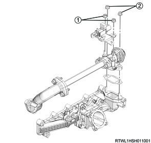
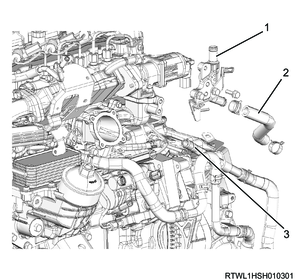
2. Euro4 specifications
1) Install the inlet cover and EGR to the cylinder head in the order shown in the diagram.
Tightening torque: 25 N・m { 2.5 kgf・m / 18 lb・ft }

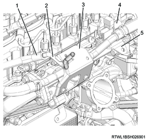
2) Install the harness bracket to the inlet cover.
Note
- Install the harness bracket so that the detent makes full contact with the inlet cover.
Tightening torque: 25 N・m { 2.5 kgf・m / 18 lb・ft }
Legend
- Inlet cover
- Detent
3) Install the air duct bracket to the inlet cover.
Tightening torque: 25 N・m { 2.5 kgf・m / 18 lb・ft }
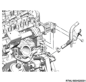
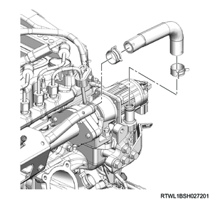
4) Install the vacuum pipe to the air duct bracket.
Tightening torque: 10.0 N・m { 1.0 kgf・m / 89 lb・in }
5) Connect the vacuum hose to the vacuum pipe.
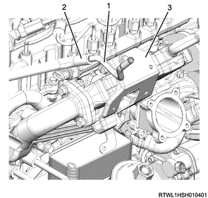
Legend
- Vacuum pipe
- Vacuum hose
- Air duct bracket
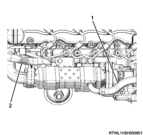
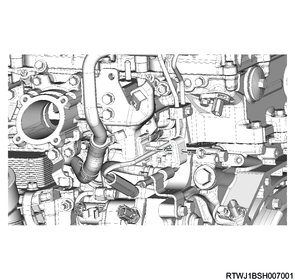
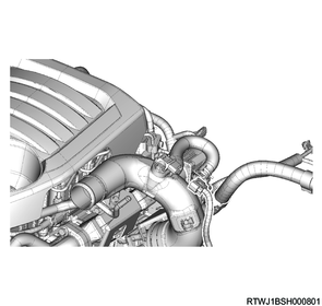
5. EGR cooler water hose connect
1. Euro4 specifications
1) Install EGR cooler water pipe A to the inlet cover.
Tightening torque: 25 N・m { 2.5 kgf・m / 18 lb・ft }
2) Connect the EGR cooler water hose to EGR cooler water pipe A.
Manual transmission models
Legend
- EGR cooler water pipe A
- EGR cooler water hose
- EGR cooler water pipe B
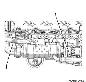
Automatic transmission models
Legend
- EGR cooler water pipe A
- EGR cooler water hose
- Water pipe
3) Connect the EGR cooler water return hose to the EGR cooler.
4) Connect the EGR cooler water feed hose to the EGR cooler.
Manual transmission models
Legend
- EGR cooler water return hose
- EGR cooler water feed hose
Automatic transmission models
Legend
- EGR cooler water return hose
- EGR cooler water feed hose
6. Water pipe installation
1. Except for Euro4 specifications
1) Install the water pipe to the inlet cover.
Tightening torque: 25 N・m { 2.5 kgf・m / 18 lb・ft }
Manual transmission models
Automatic transmission models
2) Install the pipe clip to the water pipe.
Tightening torque: 25 N・m { 2.5 kgf・m / 18 lb・ft }
3) Install the water pipe to the air duct bracket.
Tightening torque: 10.0 N・m { 1.0 kgf・m / 89 lb・in }
4) Install the water hose to the water pipe.
Manual transmission models

Automatic transmission models
5) Install the vacuum pipe to the air duct bracket.
Tightening torque: 10.0 N・m { 1.0 kgf・m / 89 lb・in }
6) Connect the vacuum hose to the vacuum pipe.
Euro2 specifications
Legend
- Vacuum pipe
- Vacuum hose
- Bracket
Except for Euro2 specifications
Legend
- Vacuum hose
- Vacuum pipe
- Bracket
- Relief valve control solenoid valve
- Relief valve control solenoid valve bracket
7. Oil level gauge guide tube installation
1) Apply engine oil to the O-ring.
2) Install the oil level gauge guide tube to the crankcase.
Tightening torque: 25 N・m { 2.5 kgf・m / 18 lb・ft }
3) Install the oil level gauge to the oil level gauge guide tube.
8. Intake throttle valve installation
9. Intake air duct installation
1) Install the intake duct to the intake throttle valve.
Tightening torque: 10.0 N・m { 1.0 kgf・m / 89 lb・in } Bolt
Tightening torque: 4.0 N・m { 0.4 kgf・m / 35 lb・in } Clamp (Intake throttle side)
Clamp installation direction
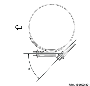
Standard value
a: 45 °
2) Connect the connector to the boost pressure and CAC temperature sensor.
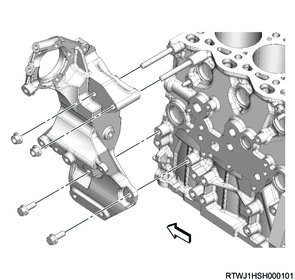
10. Generator bracket installation
1) Install the generator bracket to the cylinder block.
Tightening torque: 52 N・m { 5.3 kgf・m / 38 lb・ft }
11. A/C compressor connect
1) Connect the A/C compressor to the generator bracket.
Tightening torque: 51 N・m { 5.2 kgf・m / 38 lb・ft }
2) Connect the pipe clip to the air duct bracket.