1. Component views
Front drive axle

Part name
- Nut
- Front propeller shaft
- Nut
- Front drive axle
- Washer
- Mounting bolt
- Bolt
- Suspension cross member
- Mounting nut
- Knuckle and dust cover
- Tie rod end
- Front hub and front disc brake
Tightening torque
1: 59 N・m { 6.0 kgf・m / 44 lb・ft }
3: 59 N・m { 6.0 kgf・m / 44 lb・ft }
6: 169 N・m { 17.2 kgf・m / 125 lb・ft }
7: 26 N・m { 2.7 kgf・m / 19 lb・ft }
9: 167 N・m { 17.0 kgf・m / 123 lb・ft }
2. Shift on the fly system safety information
When assembling, if nothing in particular is specified, refer to the following and apply or add shift-on-the-fly system oil.
Refer to "201.General Information 14B.Vehicle Information recommended fluids, lubricants and diesel fuels".
3. Final drive installation
1) Clean the mating surfaces of the front drive axle and differential carrier.
2) Apply ThreeBond 1215 or equivalent to the mating surface of the front drive axle and differential carrier.
3) Install the final drive to the front drive axle.
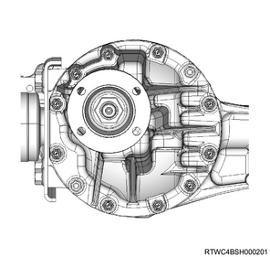
Caution
- Do not reuse the bolt.
Tightening torque: 26 N・m { 2.7 kgf・m / 19 lb・ft }
4. Inner drive shaft installation
1) Clean the housing contact surface of the front axle case.
2) Install the inner drive shaft to the front axle case.
Caution
- Install so that the inner drive shaft is not damaged.
3) Install the snap ring to the front axle case groove.
4) Apply shift-on-the-fly system oil to the sleeve.
5) Install the sleeve to the axle shaft.
5. Clutch gear installation
1) Apply shift-on-the-fly system oil to the clutch gear.
2) Install the clutch gear to the inner drive shaft.
3) Apply differential oil to the sleeve.
4) Install the sleeve to the inner drive shaft.
5) Remove any old sealing agent from the following parts.
- Mating surface of the housing and front axle case
- Bolt and threaded hole
6) Apply LOCTITE FMD-127 or equivalent to the following parts.
- Mating surface of the housing and front axle case
- Bolt and threaded hole

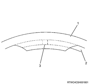
Legend
- LOCTITE FMD-127 application range
Dimensions
a. Diameter 106 mm {4.17 in}
b. Diameter 83 mm {3.27 in}
7) Install the housing to the front axle case.
Tightening torque: 75 N・m { 7.6 kgf・m / 55 lb・ft }
6. Inside drive shaft installation
1) Remove any old sealing agent from the following parts.
- Mating surface of the axle mounting bracket and front axle case
- Mating surface of the axle mounting bracket and housing
- Bolt and threaded hole
2) Apply LOCTITE FMD-127 or equivalent to the following parts.
- Mating surface of the axle mounting bracket and front axle case
- Bolt and threaded hole

Legend
- Section where application of LOCTITE FMD-127 is inhibited
- LOCTITE FMD-127 application range
Dimensions
a. Diameter 63.5 mm {2.50 in}
b. Diameter 82 mm {3.23 in}
3) Install the inside drive shaft to the front axle case and housing.
Tightening torque: 88 N・m { 9.0 kgf・m / 65 lb・ft }
7. Outside drive shaft installation
1) Fill the outside drive shaft double offset joint section with grease.
Standard: 135 g { 4.8 oz }
2) Install the outside drive shaft to the inside drive shaft.
3) Move the outside drive shaft double offset joint section in the vertical direction several times.
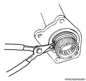
4) Install the circlip to the double offset joint case.
Note
- Install so that the circlip open end is away from the ball groove of the double offset joint case.
Legend
- Circlip
Legend
- Double offset joint case
- Circlip
- Open edge
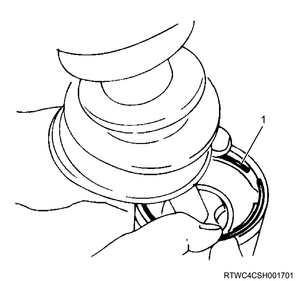
5) Install large boot band A to boot A.
Caution
- Do not reuse large boot band A.
- Install large boot band A in the correct direction.
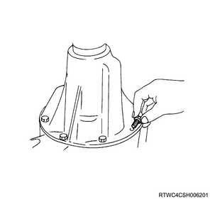
6) Stake large boot band A using the special tool.
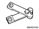
SST: 5-8840-2745-0 - clamp plier
Standard: 0.4 mm or less { 0.016 in or less } Difference between a and b
Standard stake amount
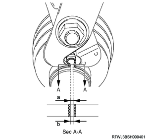
Dimensions
a: 1.2 to 4.0 mm { 0.05 to 0.16 in }
b: 1.2 to 4.0 mm { 0.05 to 0.16 in }