1. Component views
EGR cooler
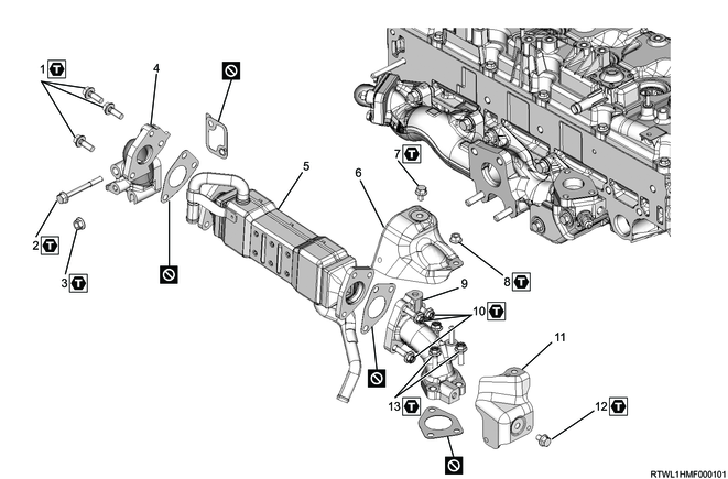
Part name
- Bolt
- Bolt
- Nut
- EGR duct
- EGR cooler
- Upper heat protector
- Bolt
- Nut
- EGR duct
- Bolt
- Lower heat protector
- Bolt
- Bolt
Tightening torque
1: 27 N・m { 2.8 kgf・m / 20 lb・ft }
2: 27 N・m { 2.8 kgf・m / 20 lb・ft }
3: 27 N・m { 2.8 kgf・m / 20 lb・ft }
7: 25 N・m { 2.5 kgf・m / 18 lb・ft }
8: 25 N・m { 2.5 kgf・m / 18 lb・ft }
10: 27 N・m { 2.8 kgf・m / 20 lb・ft }
12: 25 N・m { 2.5 kgf・m / 18 lb・ft }
13: 27 N・m { 2.8 kgf・m / 20 lb・ft }
2. EGR cooler installation
1) Temporarily tighten the EGR duct and gasket to the EGR cooler in the order shown in the diagram.
Caution
- Do not reuse the gasket.
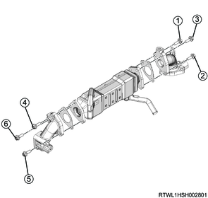
2) Final tighten the EGR duct to the EGR cooler in the order shown in the diagram.
Tightening torque: 27 N・m { 2.8 kgf・m / 20 lb・ft }
3) Install the EGR duct gasket to the cylinder head.
Caution
- Do not reuse the gasket.
Note
- Face the protruding section of the gasket toward the upper side of the engine.

Legend
- Protrusion
4) Temporarily tighten the EGR cooler and gasket to the cylinder head and exhaust manifold in the order shown in the diagram.
Caution
- Do not reuse the gasket.
5) Final tighten the EGR cooler to the cylinder head and exhaust manifold in the order shown in the diagram.
Tightening torque: 27 N・m { 2.8 kgf・m / 20 lb・ft }
6) Install the harness bracket to the EGR duct.
Tightening torque: 25 N・m { 2.5 kgf・m / 18 lb・ft }
7) In the order shown in the diagram, temporarily tighten the heat protector to the EGR duct.
8) In the order shown in the diagram, final tighten the heat protector to the EGR duct.
Tightening torque: 25 N・m { 2.5 kgf・m / 18 lb・ft }
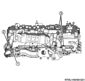
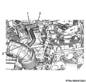
3. EGR cooler water hose connect
1) Connect the EGR cooler water return hose to the EGR cooler.
2) Connect the EGR cooler water feed hose to the EGR cooler.

Legend
- EGR cooler water return hose
- EGR cooler water feed hose
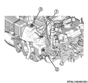
4. Differential pressure sensor bracket installation
1) Install the differential pressure sensor bracket to the cylinder head cover.
Tightening torque: 25 N・m { 2.5 kgf・m / 18 lb・ft }
2) Install the harness bracket to the cylinder head cover.
Tightening torque: 25 N・m { 2.5 kgf・m / 18 lb・ft }
3) Connect the following sensor harnesses to the harness bracket.
- Exhaust gas temperature sensor 1 (Front of DPD filter)
- Exhaust gas temperature sensor 2 (Front of oxidation catalyst)
- Heated oxygen sensor
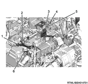
Legend
- Harness bracket
- Exhaust gas temperature sensor 1 (Front of DPD filter)
- Differential pressure sensor bracket
- Heated oxygen sensor
- Exhaust gas temperature sensor 2 (Front of oxidation catalyst)
- Harness bracket
5. Exhaust differential pressure sensor installation
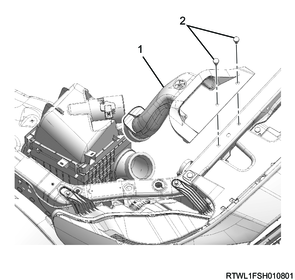
6. Air cleaner installation
1) Install the air cleaner to the vehicle.
Tightening torque: 20 N・m { 2.0 kgf・m / 15 lb・ft }
2) Connect the connector to the MAF and IAT sensor.
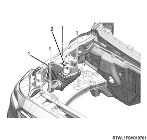
Legend
- Air cleaner
- MAF and IAT sensor
7. Air duct installation
1) Align the air duct with the air cleaner and turbocharger.
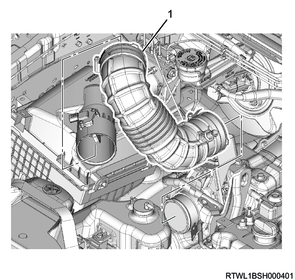
Legend
- Air duct
2) Referring to the diagram, align the alignment mark positions and connect the air duct to the turbocharger.
Tightening torque: 4.0 N・m { 0.4 kgf・m / 35 lb・in }
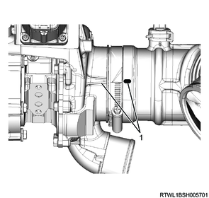
Legend
- Alignment mark
3) Install the PCV hose to the cylinder head cover and air duct.
Caution
- Align the marks on the pipe side and hose side.
Legend
- PCV hose
- Clamp
4) Install the intake air duct to the air cleaner and radiator core support.
Legend
- Intake air duct
- Clip
8. Engine cover installation
1) Install the engine cover to the engine.

Legend
- Engine cover
9. Underguard installation
10. Preliminary and post procedures
1. Post procedures
1) Lower the vehicle.
2) Connect the battery cable to the battery negative terminal.
3) Referring to the following, perform the setting of the front door power window switch with AUTO UP/AUTO DOWN function.
Refer to "9.Body, Cab, Accessories 9T.Glass, Windows, Mirrors front door power window switch setting".
4) Close the engine hood.
11. Coolant filling
1) Fill with engine coolant up to the radiator filler neck.
Note
- Fill with engine coolant of the specified concentration to the brim of the radiator cap inlet.
Caution
- Fill slowly to prevent air from entering the system.
2) While pressing the radiator upper hose manually several times to bleed the air from the hose, fill the radiator with engine coolant.
Note
- Fill with engine coolant up to the brim of the radiator cap inlet with the amount the engine coolant lowers.
Caution
- Repeat the operation until the coolant level no longer drops.
3) Add engine coolant up to the MAX line of the radiator reserve tank.
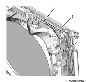
Legend
- Radiator reserve tank
- MAX line
- MIN line
4) Install the radiator cap to the radiator.
5) Start and idle the engine.
Caution
- Idle the engine for 5 minutes or more.
6) Stop the engine.
7) Remove the radiator cap from the radiator.
Warning
- Do not loosen the radiator cap or reserve tank cap when coolant is hot, as doing so may result in burns caused by the release of steam or hot water.
- When opening the radiator cap, cover the cap with a thick cloth once the engine coolant has cooled and slowly turn to release pressure.
8) Fill with engine coolant up to the radiator filler neck.
Note
- If the engine coolant is excessively low, inspect for engine coolant leakage from the cooling system.
9) Install the radiator cap to the radiator.
10) Start the engine.
11) Increase the engine speed to around 2000 rpm and run the engine for 10 minutes once the engine coolant temperature gauge reaches the center.
12) With the engine running, check that the thermostat valve is open.
Note
- Touch the radiator upper hose, and confirm that it has become warm.
- If it has not become warm, go back to Step 11.
Caution
- Do not try determining it by using only an engine coolant temperature gauge.
13) Idle the engine for 5 minutes.
14) Stop the engine.
15) Remove the radiator cap from the radiator.
Warning
- Do not loosen the radiator cap or reserve tank cap when coolant is hot, as doing so may result in burns caused by the release of steam or hot water.
- When opening the radiator cap, cover the cap with a thick cloth once the engine coolant has cooled and slowly turn to release pressure.
16) Fill with engine coolant up to the radiator filler neck.
Note
- Fill with engine coolant of the specified concentration to the brim of the radiator cap inlet.
17) Add engine coolant up to the MAX line of the radiator reserve tank.
18) Install the radiator cap to the radiator.
19) Repeat steps 10 to 18 until the coolant level no longer lowers.
Caution
- If the level of the radiator reserve tank has fallen the next morning, add up to the MAX line.