1. Component views
Timing gear case
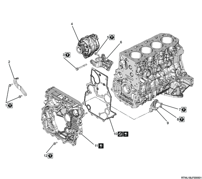
Part name
- Bolt
- Upper generator bracket
- Through bolt
- Generator
- Bolt
- Lower generator bracket
- Bolt
- Bolt
- Timing gear case bracket
- Gasket
- Timing gear case
- Bolt
Tightening torque
1: 25 N・m { 2.5 kgf・m / 18 lb・ft }
3: 40 N・m { 4.1 kgf・m / 30 lb・ft }
5: 51 N・m { 5.2 kgf・m / 38 lb・ft }
7: 25 N・m { 2.5 kgf・m / 18 lb・ft }
8: 25 N・m { 2.5 kgf・m / 18 lb・ft }
12: 25 N・m { 2.5 kgf・m / 18 lb・ft }
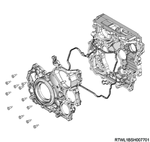
2. Timing gear case installation
1) Apply ThreeBond 1207B or equivalent to the gasket.
2) Referring to the diagram, apply ThreeBond 1207B or equivalent to the cylinder block.
Caution
- Install the timing gear case within 5 minutes of applying liquid gasket.
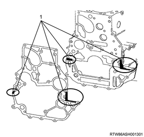
Legend
- Liquid gasket application area
3) Install the gasket to the cylinder block.
Caution
- Do not reuse the gasket.
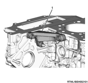
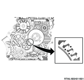
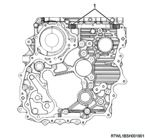
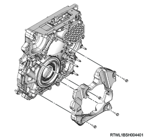
4) Align the positions of the dowel pin and bolt, and install the timing gear case to the cylinder block.
Caution
- Do not remove the bolts indicated by the arrows in the diagram when removing or installing the timing gear case.
Tightening torque: 25 N・m { 2.5 kgf・m / 18 lb・ft }
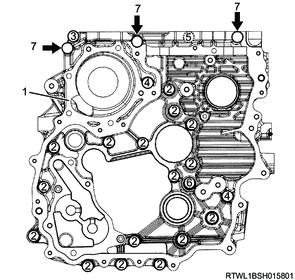
Legend
- Timing gear case
- Bolt L = 25 mm {0.98 in}
- Bolt L = 60 mm {2.36 in}
- Bolt L = 45 mm {1.77 in}
- Bolt L = 35 mm {1.38 in}
- Bolt L = 16 mm {0.63 in}
- Bolt not to be removed
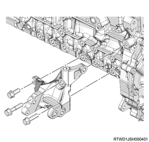
5) Temporarily tighten the timing gear case bracket to the timing gear case.
6) Temporarily tighten the timing gear case bracket to the cylinder block.
7) Final tighten the timing gear case bracket to the timing gear case.
Tightening torque: 25 N・m { 2.5 kgf・m / 18 lb・ft }
8) Final tighten the timing gear case bracket to the cylinder block.
Tightening torque: 25 N・m { 2.5 kgf・m / 18 lb・ft }
Legend
- Timing gear case bracket
3. Fuel supply pump installation
1) Apply soapy water to the O-ring.
Caution
- Do not reuse the O-ring.
2) Install the O-ring to the fuel supply pump.
3) Do not pinch the O-ring.
Tightening torque: 25 N・m { 2.5 kgf・m / 18 lb・ft }
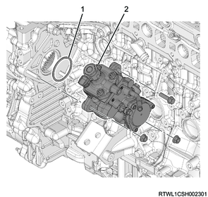
Legend
- O-ring
- Fuel supply pump
4) Connect the connector to the fuel supply pump.
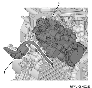
Legend
- Fuel supply pump connector
- Fuel supply pump
4. Idle gear installation
1) Apply engine oil to the gear assembly sections of the idle gear C shaft.
2) Install the idle gear C shaft to the timing gear case.
3) Apply engine oil to the threaded portion and seating surface of the idle gear C bolt.
4) Temporarily tighten idle gear C to the idle gear C shaft.
Caution
- Install so that the pink paint can be seen.

5) Apply engine oil to the idle gear A shaft.
6) Install the idle gear A shaft to the timing gear case by aligning the cylinder block side oil hole with the idle gear A shaft oil hole.
Legend
- Front mark
- Cylinder block side oil hole
- Idle gear A shaft oil hole
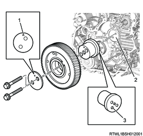
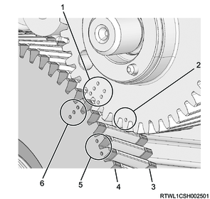
7) Install idle gear A to the idle gear A shaft.
Caution
- Do not align the 4 circular marks of idle gear A shown in the following diagram with the marks of the supply pump gear.
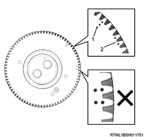
Legend
- Supply pump installation or removal position (Idle gear A side)
- TDC position (Idle gear A side)
8) Apply engine oil to the tooth surface of idle gear A.
9) Install the flange to idle gear A with the front mark facing toward the front.
10) Apply engine oil to the threaded portions and seating surfaces of the bolts, and then temporarily tighten the bolts.
11) Install the crank gear to the crankshaft.
Note
- Install after aligning with the idle gear alignment marks.
12) Final tighten idle gear A to the idle gear A shaft.
Tightening torque: 32 N・m { 3.3 kgf・m / 24 lb・ft }
13) Final tighten idle gear C to the idle gear C shaft.
Tightening torque: 59 N・m { 6.0 kgf・m / 44 lb・ft }
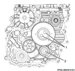
Legend
- Idle gear A bolt
- Idle gear C bolt
5. Supply pump gear installation
1) Align 3 marks on the supply pump gear and idle gear A, and install the supply pump gear to the supply pump shaft.
Caution
- Check that the supply pump gear is securely engaged with the main and sub gears of idle gear A.
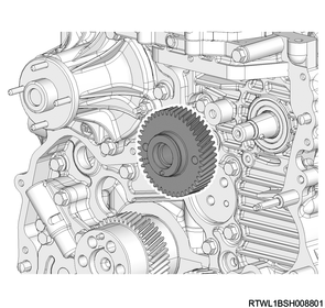
Legend
- Supply pump installation or removal position (Supply pump gear side)
- TDC position (Supply pump gear side)
- Sub-gear
- Sub-gear
- TDC position (Idle gear A side)
- Supply pump installation or removal position (Idle gear A side)
6. Oil pump installation
1) Apply engine oil to the oil pump gear.
2) Install the oil pump to the timing gear case.
Tightening torque: 25 N・m { 2.5 kgf・m / 18 lb・ft }
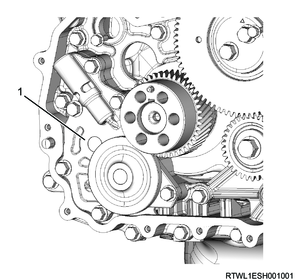
Legend
- Oil pump
7. Gear case cover installation
1) Referring to the diagram, apply ThreeBond 1207B to the timing gear case.
Caution
- Install the gear case cover within 5 minutes of applying liquid gasket.
Legend
- Liquid gasket application area
2) Install the gasket to the gear case cover.
Caution
- Do not reuse the gasket.
3) Install the gear case cover to the timing gear case.
Tightening torque: 8.0 N・m { 0.8 kgf・m / 71 lb・in }
4) Install the cover to the gear case cover.
Tightening torque: 10.0 N・m { 1.0 kgf・m / 89 lb・in }
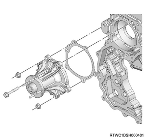
8. Water pump installation
1) Install the water pump and gasket to the timing gear case.
Caution
- Do not reuse the gasket.
Tightening torque: 25 N・m { 2.5 kgf・m / 18 lb・ft }
9. Tension pulley installation
1) Install the generator lower bracket to the cylinder block and timing gear case.
Tightening torque: 51 N・m { 5.2 kgf・m / 38 lb・ft }
2) Temporarily tighten the tension pulley to the generator bracket in the order shown in the diagram.
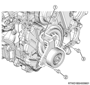
3) Final tighten the tension pulley to the generator bracket in the order shown in the diagram.
Tightening torque: 51 N・m { 5.2 kgf・m / 38 lb・ft }
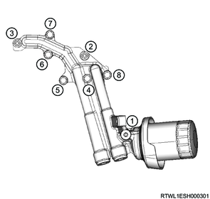
10. Oil filter installation
1) Temporarily tighten the oil filter and gasket to the oil cooler in the order shown in the diagram.
Caution
- Do not reuse the gasket.
- Ensure that no dirt or foreign material enters.
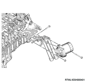
2) Final tighten the oil filter to the oil cooler in the order shown in the diagram.
Tightening torque: 25 N・m { 2.5 kgf・m / 18 lb・ft }
11. Crankshaft pulley installation
1) Apply engine oil to the threaded portions and seating surfaces of the bolts.
2) Install the crankshaft pulley to the crankshaft in the order shown in the diagram.
Note
- Install the crankshaft pulley aligned with the knock pin of the crankshaft.
Caution
- Do not reuse the crankshaft pulley bolt and washer.
Tightening torque: 30 N・m { 3.1 kgf・m / 22 lb・ft } 1st time
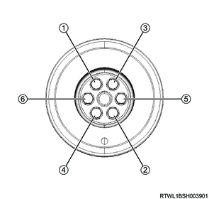
3) Retighten the bolts in the order shown in the diagram using the special tool.

SST: 5-8840-0266-0 - angle gauge
Tightening Angle : 180 ° 2nd time
4) Retighten the bolts in the order shown in the diagram using the special tool.
SST: 5-8840-0266-0 - angle gauge
Tightening Angle : 60 ° 3rd time
5) Remove the special tool from the starter installation section of the rear plate.
12. Power steering oil pump connect
1) Install the power steering oil pump to the timing gear case.
Tightening torque: 25 N・m { 2.5 kgf・m / 18 lb・ft }
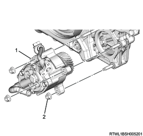
Legend
- Power steering oil pump
- Nut
2) Install the power steering oil hose to the bracket.
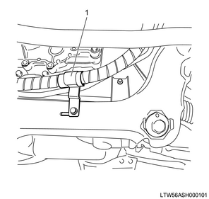
Legend
- Bracket
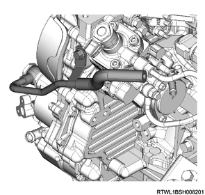
13. Fuel leak-off pipe installation
1) Install the fuel leak-off pipe to the fuel supply pump and common rail (fuel rail).
Tightening torque: 10.3 N・m { 1.1 kgf・m / 91 lb・in } Fuel supply pump side
Tightening torque: 25 N・m { 2.5 kgf・m / 18 lb・ft } Cylinder block side
Tightening torque: 10.3 N・m { 1.1 kgf・m / 91 lb・in } Common rail (fuel rail) side
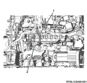
Legend
- Leak-off hose
- Fuel leak-off pipe
14. Fuel feed pipe installation
1) Install the fuel feed pipe to the fuel supply pump and common rail (fuel rail).
Caution
- Do not reuse the fuel feed pipe.
Tightening torque: 44 N・m { 4.5 kgf・m / 32 lb・ft }
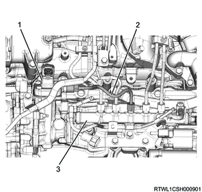
Legend
- Fuel supply pump
- Fuel feed pipe
- Common rail (fuel rail)
15. Vacuum pump installation
1) Install the vacuum pump to the gear case cover.
Tightening torque: 25 N・m { 2.5 kgf・m / 18 lb・ft }
2) Install the vacuum pump oil pipe to the vacuum pump and cylinder block.
Tightening torque: 12 N・m { 1.2 kgf・m / 106 lb・in }
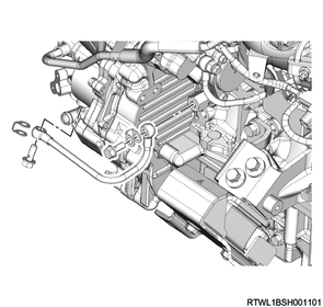
3) Install the vacuum pipe as a set with the vacuum hose to the timing gear case and vacuum pump.
Tightening torque: 32 N・m { 3.3 kgf・m / 24 lb・ft } Vacuum pump side
Tightening torque: 25 N・m { 2.5 kgf・m / 18 lb・ft } Timing gear case side