1. Component views
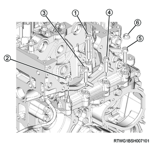
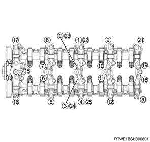
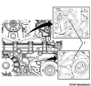
Cylinder head
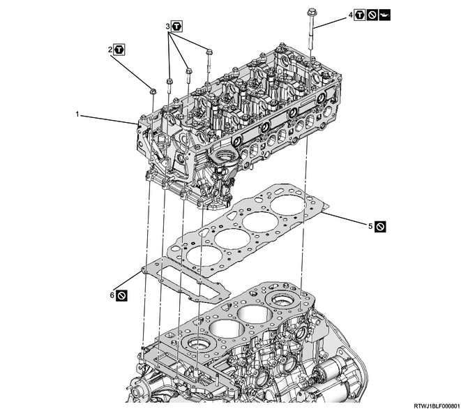
Part name
- Cylinder head
- Gear case nut
- Gear case bolt
- Cylinder head bolt
- Cylinder head gasket
- Timing gear case gasket
Tightening torque
2: 25 N・m { 2.5 kgf・m / 18 lb・ft }
3: 25 N・m { 2.5 kgf・m / 18 lb・ft }
4-1: 70 N・m { 7.1 kgf・m / 52 lb・ft }
4-2: 70 N・m { 7.1 kgf・m / 52 lb・ft }
4-3: 60 to 75 °
4-4: 60 to 75 °
2. Cylinder head installation
1) Clean the upper surface of the cylinder block and lower surface of the cylinder head using a scraper.
Caution
- Do this carefully so as to not damage the upper surface of the cylinder block or lower surface of the cylinder head.
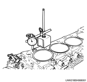
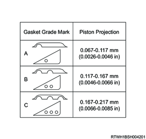
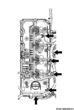
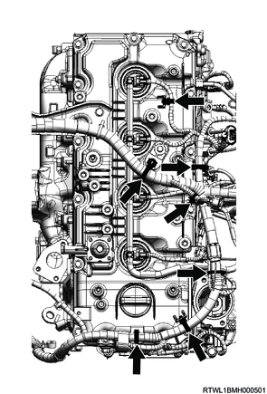
2) Measure the protrusion amount of the piston head using a dial gauge.
Caution
- The measurement point should be as close to the cylinder block as possible.
- The difference between the protruding amount of each piston must be within the specified range.
Standard: 0.05 mm or less { 0.0020 in or less }
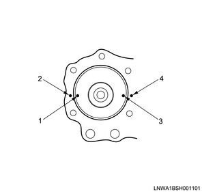
Legend
- Measurement point
- Measurement point
- Measurement point
- Measurement point
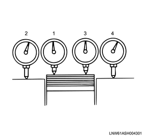
Legend
- Measurement point
- Measurement point
- Measurement point
- Measurement point
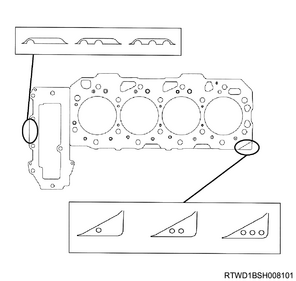
3) Select the grade of the cylinder head gasket and timing gear case gasket based on the average of the measured values.
Caution
- Do not reuse the cylinder head gasket and timing gear case gasket.
4) Apply ThreeBond 1207B or equivalent to the positions on the cylinder block shown in the diagram.
Caution
- After applying the liquid gasket, install the cylinder head within 5 minutes.
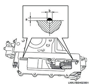
Standard value
a: 2.0 to 3.0 mm { 0.079 to 0.118 in } Bead height
b: 3.0 to 4.0 mm { 0.118 to 0.157 in } Bead width
5) Place the cylinder head gasket and timing gear case gasket on the cylinder block.
Caution
- Do not reuse the cylinder head gasket and timing gear case gasket.
6) Align the dowel positions, and place the cylinder head on the cylinder block.
Caution
- Do not damage the cylinder head gasket and timing gear case gasket.
7) Apply engine oil to the threaded portions and seating surfaces of the cylinder head mounting bolts.
Caution
- Do not reuse the cylinder head bolts.
8) Tighten the cylinder head bolts to the cylinder head using the special tool and a torque wrench in the order shown in the diagram.
SST: 5-8840-0266-0 - angle gauge
Tightening torque: 70 N・m { 7.1 kgf・m / 52 lb・ft } 1st time
Tightening torque: 70 N・m { 7.1 kgf・m / 52 lb・ft } 2nd time
Note
- Retighten to the same torque to prevent variations in the tightening torque.
Tightening Angle : 60 to 75 ° 3rd time
Tightening Angle : 60 to 75 ° 4th time

9) Install the nuts and bolts to the timing gear case in the order shown in the diagram.
Tightening torque: 25 N・m { 2.5 kgf・m / 18 lb・ft }
10) Remove the wire from the engine hanger and hoist.
11) Remove special tool from the cylinder head.
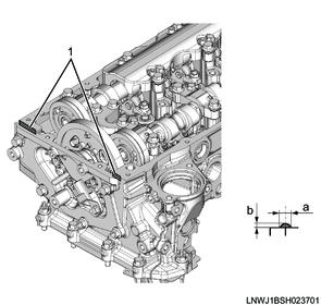
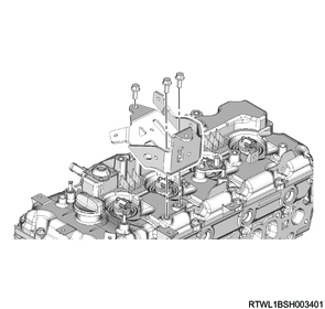
3. Camshaftbracket installation
1) Rotate the crankshaft in the forward direction (clockwise) to align the No. 1 cylinder piston to compression top dead center.
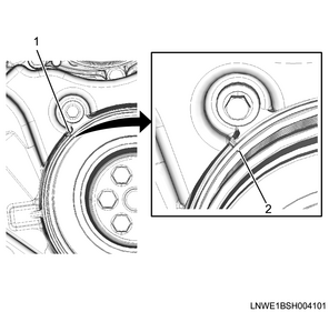
Legend
- Top dead center alignment mark on the gear case cover side
- Crankshaft pulley side top dead center alignment mark
2) Align the camshaft bracket to the cylinder head.
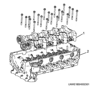
Legend
- Camshaft bracket
- Cylinder head
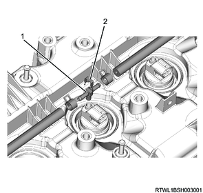
3) Align the marks of the inlet camshaft and exhaust camshaft with the mark of the bearing cap.
Caution
- Confirm that the valve cap is correctly installed to the valve stem end.
- Be careful of valve cap detachment or looseness.
Legend
- Alignment mark
4) Apply engine oil to the threaded portions and seating surfaces of the M8 bolts.
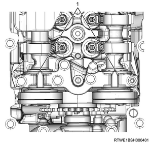
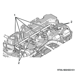
5) Tighten the camshaft bracket bolts in the order shown in the diagram.
Tightening torque: 18 N・m { 1.8 kgf・m / 13 lb・ft } Wet
4. Rocker arm adjustment
1) Rotate the crankshaft in the forward direction (clockwise) to align the No. 1 cylinder piston to compression top dead center.
Legend
- Top dead center alignment mark on the gear case cover side
- Crankshaft pulley side top dead center alignment mark
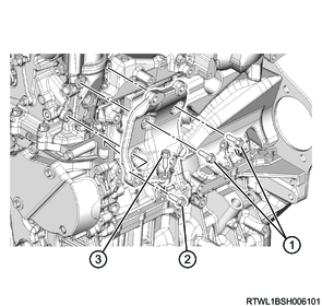
2) Loosen the adjust screw of the rocker arm using the special tool.
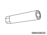
SST: 5-8840-2822-0 - valve clearance adjust nut wrench
Legend
- Screwdriver
- Ring spanner
- 5-8840-2822-0
3) Insert a feeler gauge between the rocker arm roller and the cam.
Note
- Tighten the rocker arm adjust screw, and adjust the valve clearance to the standard value.
Standard: 0.15 mm { 0.0059 in } When cold
4) Lightly tighten the adjust screw with the feeler gauge inserted using the special tool.
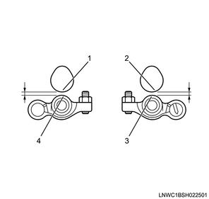
Legend
- Cam (Exhaust side)
- Cam (Inlet side)
- Roller (Inlet side)
- Roller (Exhaust side)
5) Verify that the movement of the feeler gauge becomes stiff.
6) Secure the rocker arm adjust screw with the adjust screw nut.
Tightening torque: 18 N・m { 1.8 kgf・m / 13 lb・ft }
| Cylinder position |
#1 |
#2 |
#3 |
#4 |
||||
| IN |
EX |
IN |
EX |
IN |
EX |
IN |
EX |
|
| No. 1 cylinder compression top dead center |
○ |
○ |
○ |
○ |
||||
| No. 4 cylinder compression top dead center |
○ |
○ |
○ |
○ |
||||
7) Rotate the crankshaft for 1 turn, and adjust any remaining valve clearance.
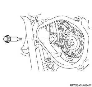
5. Timing chain installation
1) Install the timing chain guide to the cylinder head and cylinder block.
Tightening torque: 25 N・m { 2.5 kgf・m / 18 lb・ft }
Legend
- Timing chain guide bolt
2) Insert the timing chain tension lever into the gap between the timing gear case and the cylinder block.
3) Align the timing chain with the supply pump sprocket.
4) Install the sprocket and timing chain as a set to idle gear D.
Tightening torque: 8.0 N・m { 0.8 kgf・m / 71 lb・in }
5) Apply engine oil to the threaded portion and seating surface of the idle gear D shaft bolt.
6) Install the idle gear D shaft bolt and sleeve to idle gear D and sprocket.
Tightening torque: 59 N・m { 6.0 kgf・m / 44 lb・ft }
7) Align the 2 timing alignment marks at the location shown in the diagram.

Legend
- Timing chain
- Timing mark
- Blue link
- Yellow link
8) Install the timing chain lever pivot to the timing chain tension lever.
Tightening torque: 27 N・m { 2.8 kgf・m / 20 lb・ft }
9) Push down the timing chain tensioner latch and insert the plunger.
Note
- Install the hook to the pin while pressing the plunger.
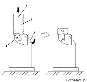
Legend
- Pin
- Plunger
- Latch
- Hook
10) Install the timing chain tensioner and gasket to the cylinder head.
Caution
- Do not reuse the gasket.
Tightening torque: 10.0 N・m { 1.0 kgf・m / 89 lb・in }
11) Install the oil feed pipe to the timing chain tensioner.
Caution
- Do not reuse the gasket.
Tightening torque: 14.7 N・m { 1.5 kgf・m / 130 lb・in }
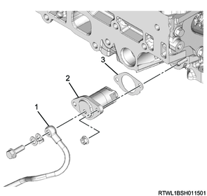
Legend
- Oil feed pipe
- Timing chain tensioner
- Gasket
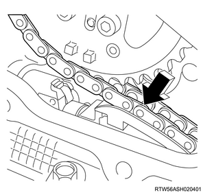
12) Lightly press the area indicated by the arrow in the diagram to disconnect the hook from the pin.
Note
- The hook of the tensioner opens and the plunger pushes the tension lever to pull the chain.
6. Timing chain lower cover installation
1) Referring to the diagram, apply ThreeBond 1207C or equivalent to the timing chain lower cover.
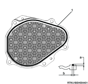
Legend
- Liquid gasket
Standard value
a: 2.0 to 2.5 mm { 0.079 to 0.098 in } Bead height
b: 2.0 to 2.5 mm { 0.079 to 0.098 in } Bead width
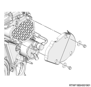
2) Install the timing chain lower cover to the gear case cover.
Tightening torque: 10.0 N・m { 1.0 kgf・m / 89 lb・in }
3) Install the noise cover to the timing chain lower cover.
Tightening torque: 10.0 N・m { 1.0 kgf・m / 89 lb・in }
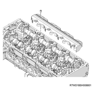
7. Timing chain upper cover installation
1) Referring to the diagram, apply ThreeBond 1207C or equivalent to the timing chain upper cover.
Caution
- Install the timing chain cover within 5 minutes of applying the liquid gasket.
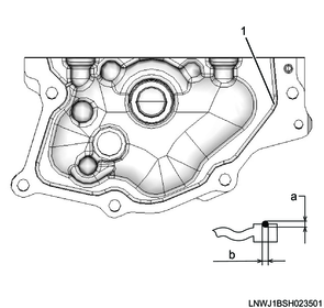
Legend
- Liquid gasket
Standard value
a: 1.0 to 1.5 mm { 0.039 to 0.059 in } Bead height
b: 2.0 to 2.5 mm { 0.079 to 0.098 in } Bead width
2) Install the timing chain upper cover to the cylinder head.
Caution
- Wipe off any excess liquid gasket.
Tightening torque: 25 N・m { 2.5 kgf・m / 18 lb・ft }
3) Connect the connector to the CMP sensor.
8. Baffle plate installation
1) Install the baffle plate to the cylinder head.
Tightening torque: 10.0 N・m { 1.0 kgf・m / 89 lb・in }
9. Glow plug installation
1) Install the glow plug to the cylinder head.
Tightening torque: 18 N・m { 1.8 kgf・m / 13 lb・ft }

Legend
- Glow plug
2) Install the glow plug terminal and glow plug connector to the glow plug.
Tightening torque: 1.0 N・m { 0.10 kgf・m / 8.9 lb・in }

Legend
- Glow plug terminal
- Glow plug connector
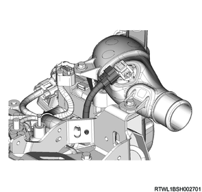
10. Thermostat installation
1) Install the thermostat to the thermostat housing with the jiggle valve facing the front of the vehicle.
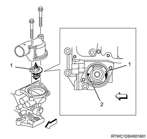
Legend
- Thermostat
- Jiggle valve
2) Install the water outlet pipe to the cylinder head.
Tightening torque: 25 N・m { 2.5 kgf・m / 18 lb・ft }
3) Connect the water hose to the water outlet pipe.
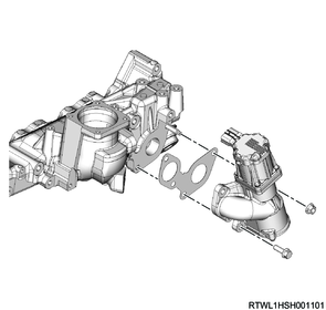
11. EGR valve installation
1) Install the EGR valve and gasket to the inlet manifold.
Caution
- Do not reuse the gasket.
Tightening torque: 27 N・m { 2.8 kgf・m / 20 lb・ft } Nut
Tightening torque: 24 N・m { 2.4 kgf・m / 18 lb・ft } Bolt
12. Intake throttle valve installation
1) Install the following parts to the inlet manifold.
Caution
- Do not reuse the gasket.
Tightening torque: 10.0 N・m { 1.0 kgf・m / 89 lb・in }
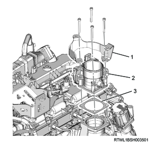
Legend
- Air duct bracket
- Intake throttle valve
- Gasket
2) Connect the connector to the intake throttle valve.
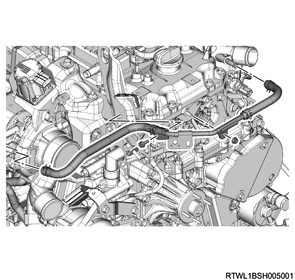
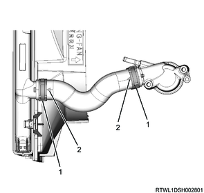
13. Water intake pipe installation
1) Temporarily tighten the water intake pipe and water hose to the oil cooler in the order shown in the diagram.
Caution
- Do not reuse the gasket.
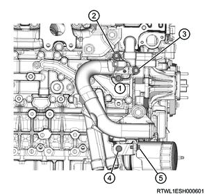
2) Final tighten the water intake pipe and water hose to the oil cooler in the order shown in the diagram.
Tightening torque: 25 N・m { 2.5 kgf・m / 18 lb・ft }
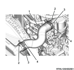
14. Radiator lower hose connect
1) Connect the radiator lower hose and clamp to the water intake pipe.
Note
- Insert the lower hose until it makes full contact with the pipe.
- Soapy water can be applied when installing the lower hose.
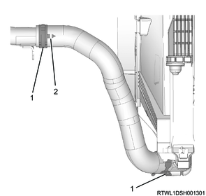
Legend
- Clamp
- Arrow mark
Note
- Align the clamp with the lower hose arrow mark end to install.
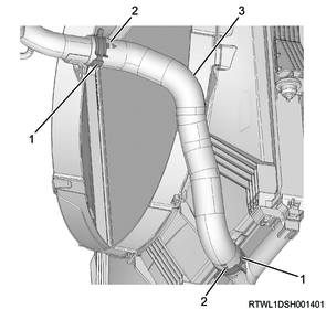
Legend
- Clamp
- Arrow mark
- Radiator lower hose
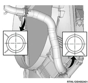
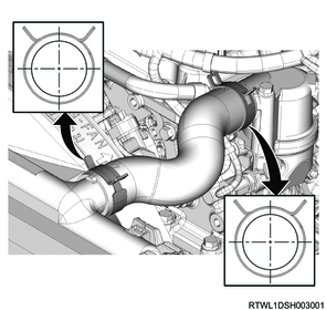
Note
- Install the clamp in the direction shown in the following diagram.
- The diagram about the clamp direction shows the state viewed from the vehicle front.
15. Water pipe installation
1) Install the water pipe to the following parts.
- Thermostat
- Cylinder head
- Turbocharger
Tightening torque: 10.0 N・m { 1.0 kgf・m / 89 lb・in } Bolt, nut
16. Tension pulley installation
1) Install the tension pulley to the cylinder head.
Tightening torque: 25 N・m { 2.5 kgf・m / 18 lb・ft }
17. Injector installation
1) Apply engine oil to the O-ring.
2) Install the O-ring to the injector.
Caution
- Do not damage the O-ring.
3) Clean the cylinder head installation surface and injector.
4) Drop the gasket into the port on the cylinder head side.
Caution
- Do not reuse the gasket.
- Check that the gasket is seated horizontally.
5) Check that the gasket has been inserted based on the nozzle height using the injector.
Caution
- Do not reuse the leak-off pipe or clip.
- Press the injector in perpendicularly to ensure that the gasket is not slanted.
- Do not hold the injector connector.
- Do not forcibly push the gasket into the injector as it will be pushed until it hits the end of the injector during clamp tightening.

Legend
- Injector
- Leak-off pipe
- Clip
- O-ring
- Gasket
6) Install the injector clamp to the injector.

Legend
- Injector
- Bolt
- Injector clamp
7) Apply engine oil to the threaded portions and seating surfaces of the bolts.
8) Install the injector and injector clamp to the cylinder head.
9) Temporarily tighten the injector clamp bolt to the cylinder head.
18. Injection pipe installation
1) Apply engine oil to the threaded portions of the sleeve nuts on the injector side, as well as the injector O-rings.
2) Temporarily tighten the injection pipes to the common rail (fuel rail) and injectors by hand until the sleeve nuts can no longer turn.
Caution
- Do not reuse the injection pipe.
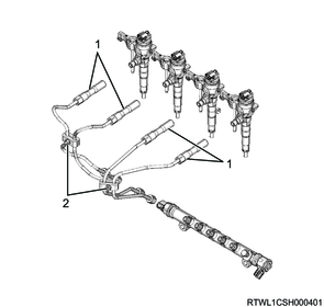
Legend
- Injection pipe
- Clip
3) Temporarily tighten the clip to the injection pipe.
4) Final tighten the injector clamp bolt to the cylinder head.
Tightening torque: 26 N・m { 2.7 kgf・m / 19 lb・ft }
5) Final tighten the injection pipes to the injectors and common rail (fuel rail).
Tightening torque: 44 N・m { 4.5 kgf・m / 32 lb・ft } Injector side
Tightening torque: 44 N・m { 4.5 kgf・m / 32 lb・ft } Common rail (fuel rail) side
6) Securely tighten the clip to the injection pipe.
Tightening torque: 8.0 N・m { 0.8 kgf・m / 71 lb・in }
19. Leak-off pipe installation
1) Install the leak-off pipe to the inlet manifold.
Tightening torque: 25 N・m { 2.5 kgf・m / 18 lb・ft }
2) Connect the 2 leak-off hoses to the leak-off pipe.
3) Connect the 3 vacuum hoses to the vacuum pipe.
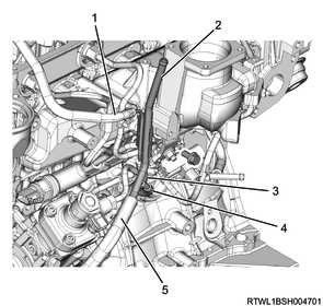
Legend
- Leak-off hose (Injector side)
- Leak-off pipe
- Leak-off hose (Supply pump side)
- Vacuum hose (Swirl control valve side)
- Vacuum hose (Vacuum pump side)
4) Temporarily tighten the harness brackets to the inlet manifold in the order shown in the diagram.

5) Final tighten the harness brackets to the inlet manifold in the order shown in the diagram.
Tightening torque: 10.0 N・m { 1.0 kgf・m / 89 lb・in }
20. Swirl control solenoid valve installation
1) Install the swirl control solenoid valve and bracket as a set to the inlet manifold.
Tightening torque: 25 N・m { 2.5 kgf・m / 18 lb・ft }
2) Connect the vacuum hose to swirl control solenoid valve.
3) Connect the connector to swirl control solenoid valve.
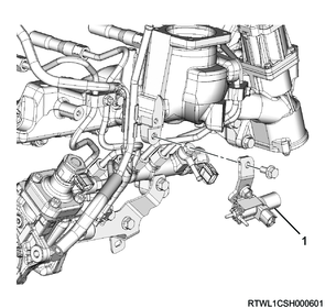
Legend
- Swirl control solenoid valve
21. Fuel hose connect
1) Connect the fuel return hose to the fuel leak-off pipe.
2) Connect the fuel feed hose to the fuel supply pump.
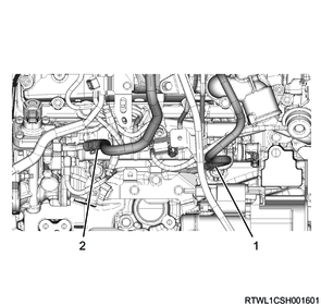
Legend
- Fuel return hose
- Fuel feed hose
22. Cylinder head cover installation
1) Apply the engine oil to the oil seal.
2) Insert the oil seal from the lower side of the cylinder head cover until it reaches the far end.
3) Referring to the diagram, apply ThreeBond 1217H or 1207C to the cylinder head mating surface.
Caution
- Install the cylinder head cover within 5 minutes of applying liquid gasket.
- Remove any dirt or dust from the oil seal section on the injector connector side.
Legend
- Liquid gasket
Standard value
a: 2.0 to 2.5 mm { 0.079 to 0.098 in } Bead width
b: 1.0 to 1.5 mm { 0.039 to 0.059 in } Bead height
4) Temporarily tighten the cylinder head cover to the cylinder head in the order shown in the diagram.
Caution
- Do not reuse the gasket.
Tightening torque: 5.0 N・m { 0.5 kgf・m / 44 lb・in }
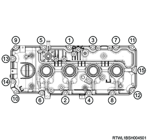
5) Final tighten the cylinder head cover to the cylinder head in the order shown in the diagram.
Tightening torque: 9.0 N・m { 0.9 kgf・m / 80 lb・in }
6) Install the harness bracket to the cylinder head cover.
Tightening torque: 25 N・m { 2.5 kgf・m / 18 lb・ft }
7) Connect the harness clip to the cylinder head cover.
RHD
LHD
8) Connect the PCV hose to the cylinder head cover.
23. Fuel leak-off hose installation
1) Install the injector leak-off pipe to the injector.
Caution
- Do not reuse the injector leak-off pipe or clip.
Legend
- Injector leak-off pipe
- Clip
2) Install the fuel leak-off hose to the leak-off pipe.
3) Connect the connector to the injector.
Legend
- Fuel leak-off hose
- Injector connector
24. Air duct bracket installation
1) Install the air duct bracket to the cylinder head cover.
Tightening torque: 25 N・m { 2.5 kgf・m / 18 lb・ft }
25. Oil level gauge guide tube installation
1) Apply engine oil to the O-ring.
Caution
- Do not reuse the O-ring.
2) Install the oil level gauge guide tube to the crankcase.
Tightening torque: 25 N・m { 2.5 kgf・m / 18 lb・ft }

3) Install the oil level gauge to the oil level gauge guide tube.
26. A/C compressor bracket installation
1) Temporarily tighten the A/C compressor bracket to the cylinder head.
2) Final tighten the A/C compressor bracket to the cylinder head in the order shown in the diagram.
Tightening torque: 25 N・m { 2.5 kgf・m / 18 lb・ft }
27. A/C compressor connect
1) Connect the A/C compressor to the A/C compressor bracket.
Tightening torque: 51 N・m { 5.2 kgf・m / 38 lb・ft }
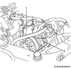
Legend
- A/C compressor bracket
- A/C compressor
28. Intake air duct installation
1) Install the intake duct to the intake throttle valve.
Tightening torque: 10.0 N・m { 1.0 kgf・m / 89 lb・in } Bolt
Tightening torque: 4.0 N・m { 0.4 kgf・m / 35 lb・in } Clamp (Intake throttle valve side)
2) Connect the air intake hose to the intercooler.
Caution
- Align the marks on the pipe side and hose side.
Tightening torque: 5.0 N・m { 0.5 kgf・m / 44 lb・in } Clamp (Intercooler side)
3) Connect the connector to the boost pressure sensor.
29. Generator installation
1) Install the generator to the lower bracket.
Tightening torque: 40 N・m { 4.1 kgf・m / 30 lb・ft }
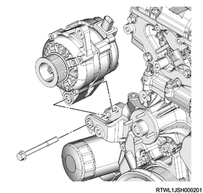
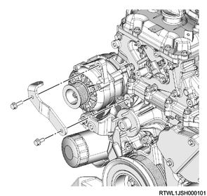
2) Install the upper bracket to the generator and timing gear case.
Tightening torque: 25 N・m { 2.5 kgf・m / 18 lb・ft }
3) Connect the connector to the generator.
4) Connect the B-terminal to the generator.
Tightening torque: 12 N・m { 1.2 kgf・m / 106 lb・in }
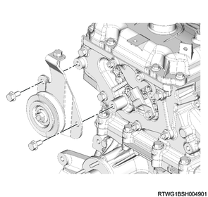
30. Cooling fan belt installation
1) Install the cooling fan belt to the following parts.
- Fan pulley
- Generator
- Crankshaft pulley
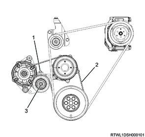
Legend
- Adjust bolt
- Cooling fan belt
- Lock nut
31. A/C compressor drive belt installation
1) Install the A/C compressor drive belt to the following parts.
- Tension pulley
- A/C compressor
- Crankshaft pulley
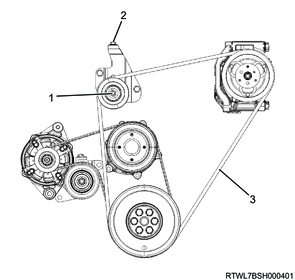
Legend
- Lock nut
- Adjust bolt
- A/C compressor drive belt
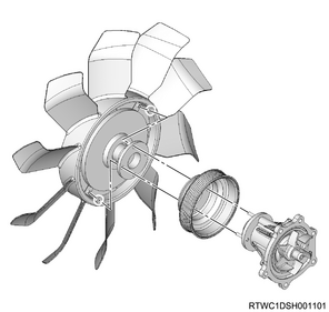
32. Cooling fan installation
1) Install the fan pulley to the water pump.
2) Install the cooling fan and cooling fan clutch as a set to the water pump.
Tightening torque: 10.0 N・m { 1.0 kgf・m / 89 lb・in }
33. Fan guide installation
1) Install the fan guide to the radiator.
Tightening torque: 6.5 N・m { 0.7 kgf・m / 58 lb・in }
2) Install the fan shroud to the fan guide.
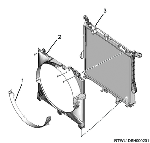
Legend
- Fan shroud
- Fan guide
- Radiator
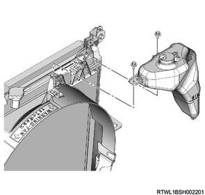
34. Radiator reserve tank installation
1) Clean the radiator reserve tank using detergent.
Note
- Wash with clean water, and drain the water.
2) Assemble the reserve tank hose to the radiator reserve tank.
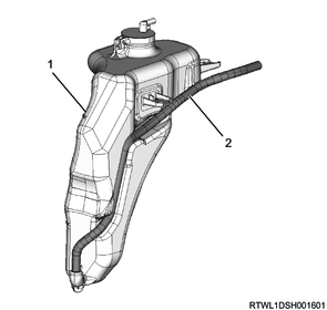
Legend
- Radiator reserve tank
- Reserve tank hose
3) Install the radiator reserve tank to the fan guide.
Tightening torque: 8.4 N・m { 0.9 kgf・m / 74 lb・in }
4) Connect the radiator reserve tank hose to the radiator.
Caution
- Assemble the reserve tank hose to the dent to fit the radiator reserve tank shape.
35. Radiator upper hose installation
1) Install the radiator upper hose and clamp to the thermostat and radiator.
Note
- Align the painted arrow on the upper hose with the pipe boss section to install.
- Insert the upper hose until it makes full contact with the pipe.
- Soapy water can be applied when installing the upper hose.
Legend
- Radiator upper hose
- Boss section
- Clamp
- Arrow mark
Note
- Align the clamp with the upper hose arrow mark end to install.
Legend
- Clamp
- Arrow mark
Note
- Install the clamp in the direction shown in the following diagram.
- The diagram about the clamp direction shows the state viewed from the vehicle front.
36. Battery installation
1) Install the battery to vehicle.
2) Install the battery bracket to the frame.
Tightening torque: 4.0 N・m { 0.41 kgf・m / 35.4 lb・in } Battery side
Tightening torque: 20 N・m { 2.0 kgf・m / 15 lb・ft } Frame side
3) Connect the battery cable to the battery.
4) Connect the battery ground cable to the frame.
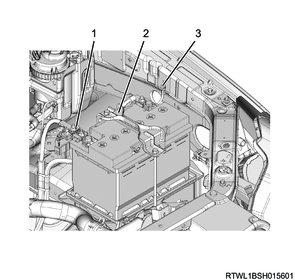
Legend
- Battery cable
- Battery bracket
- Battery ground cable
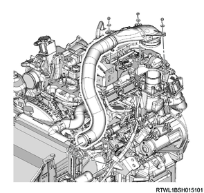
37. Turbocharger installation
38. Cowl panel installation
1) Install the cowl panel to vehicle.

39. Wiper linkage installation
40. Engine oil filling
1) Replenish the engine with the engine oil.
2) Check the tightening of the oil pan drain plug.
Tightening torque: 44 N・m { 4.5 kgf・m / 32 lb・ft }
41. Engine hood installation
42. Preliminary and post procedures
1. Post procedures
1) Lower the vehicle.
2) Connect the battery cable to the battery negative terminal.
3) Referring to the following, perform the setting of the front door power window switch with AUTO UP/AUTO DOWN function.
Refer to "9.Body, Cab, Accessories 9T.Glass, Windows, Mirrors front door power window switch setting".
4) Close the engine hood.
43. Cooling fan belt adjustment
When installing a new belt, initial stretching of the belt occurs.
In addition, when reusing the belt, the belt needs to be fitted to the pulley groove.
After fitting the cooling fan belt, readjust the cooling fan belt tension.
1) Loosen the tension pulley lock nut using a wrench.
2) Adjust the cooling fan belt tension by turning the adjust bolt.
Note
- The standard amount of deflection shown is the value obtained when the standard pressure is applied to the midpoint of the fan pulley and generator.
Standard: 98 N { 10.0 kg / 22 lb }
Caution
- Accurately adjust the tension as there is a possibility the service life of the belt may be shortened or belt squeal may be generated if the tension is not within the appropriate range.
- Use a sonic tension meter to verify accurate tension adjustment.
| Adjustment conditions |
Deflection |
Vibration frequency |
| When new |
5.0 to 6.0 mm { 0.20 to 0.24 in } |
207 to 231 Hz |
| Reused |
7.0 to 7.8 mm { 0.28 to 0.31 in } |
176 to 190 Hz |
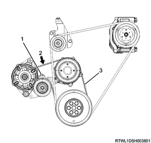
Legend
- Tension pulley adjust bolt
- Measurement point
- Cooling fan belt
3) Tighten the tension pulley lock nut to the specified torque.
Tightening torque: 41 N・m { 4.2 kgf・m / 30 lb・ft }
44. A/C compressor drive belt adjustment
When installing a new belt, initial stretching of the belt occurs.
In addition, when reusing the belt, the belt needs to be fitted to the pulley groove.
After fitting the A/C compressor drive belt, adjust the tension of the A/C compressor drive belt again.
1) Loosen the tension pulley lock nut.
2) Turn the tension pulley adjust bolt to adjust the tension.
Note
- The standard deflection shown is the value obtained when the specified load is applied to the measurement point of the A/C compressor drive belt.
98 N { 10.0 kg / 22 lb } Load
Caution
- Accurately adjust the tension as there is a possibility the service life of the belt may be shortened or belt squeal may be generated if the tension is not within the appropriate range.
- Use a sonic tension meter to verify accurate tension adjustment.
| Adjustment conditions |
Deflection |
Vibration frequency |
| When new |
12.5 to 16.5 mm { 0.49 to 0.65 in } |
92 to 112 Hz |
| Reused |
16.5 to 19.1 mm { 0.65 to 0.75 in } |
79 to 91 Hz |
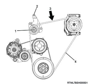
Legend
- Lock nut
- Adjust bolt
- Measurement point
- A/C compressor drive belt
3) Tighten the tension pulley lock nut to the specified torque.
Tightening torque: 51 N・m { 5.2 kgf・m / 38 lb・ft }