1. Component views
Hydraulic power steering unit
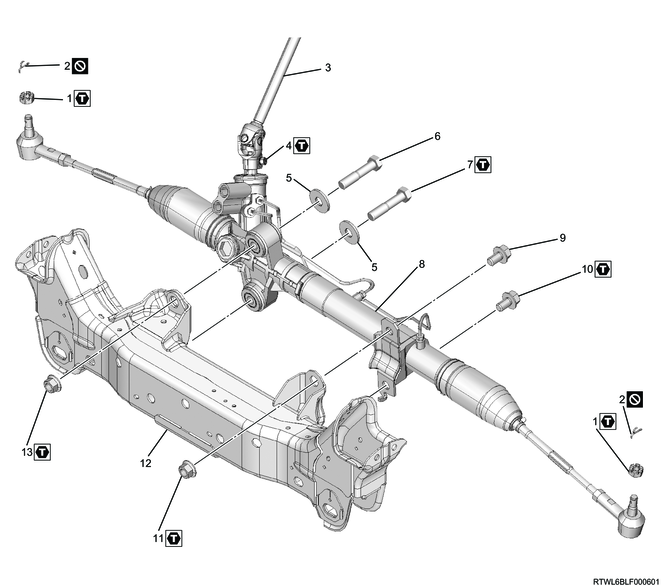
Part name
- Castle nut
- Cotter pin
- Steering shaft
- Bolt
- Washer
- Bolt
- Bolt
- Power steering unit
- Bolt
- Bolt
- Nut
- Cross member
- Nut
Tightening torque
1: 98 N・m { 10.0 kgf・m / 72 lb・ft }
4: 31 N・m { 3.2 kgf・m / 23 lb・ft }
7: 220 N・m { 22.4 kgf・m / 162 lb・ft }
10: 220 N・m { 22.4 kgf・m / 162 lb・ft }
11: 220 N・m { 22.4 kgf・m / 162 lb・ft }
13: 220 N・m { 22.4 kgf・m / 162 lb・ft }
Electric power steering unit
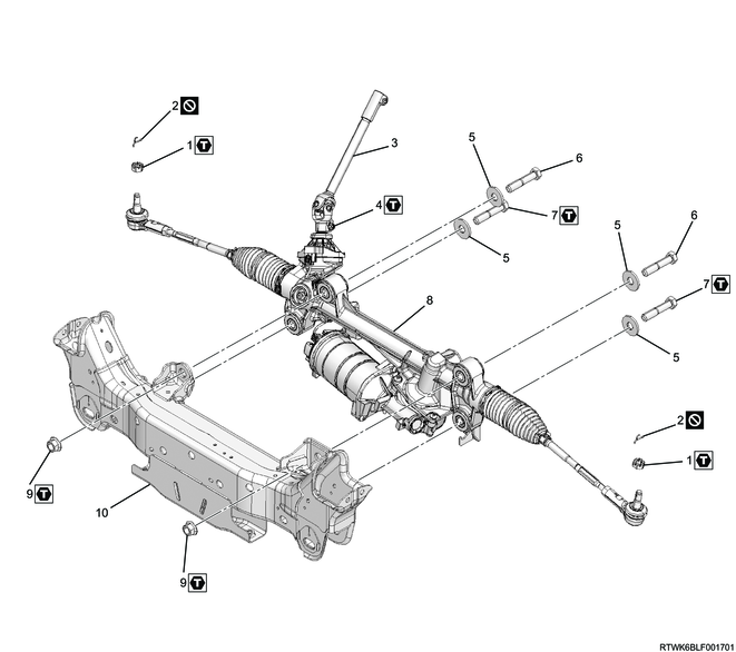
Part name
- Castle nut
- Cotter pin
- Steering shaft
- Bolt
- Washer
- Bolt
- Bolt
- Power steering unit
- Nut
- Cross member
Tightening torque
1: 98 N・m { 10.0 kgf・m / 72 lb・ft }
4: 31 N・m { 3.2 kgf・m / 23 lb・ft }
7: 220 N・m { 22.4 kgf・m / 162 lb・ft }
9: 220 N・m { 22.4 kgf・m / 162 lb・ft }
2. Preliminary and post procedures
1. Preliminary procedures
1) Open the engine hood.
2) Disconnect the battery cable from the battery negative terminal.
Caution
- After turning OFF the ignition switch (power mode for models with passive entry and start system), do not disconnect the battery cable within 3 minutes.
- If the battery cable is disconnected within 3 minutes, the vehicle electronic control system may malfunction.
- If the battery cable is disconnected, perform the setting of the front door power window switch with AUTO UP/AUTO DOWN function after connecting the battery negative terminal.
3) Raise the vehicle.
3. Underguard removal
1. Models with front and rear underguards (long type)
1) Remove the rear underguard (long type) from the frame.
2) Remove the front underguard from the frame.
Legend
- Front underguard
- Rear underguard (long type)
- Bolt
- Clip
2. Models with front and rear underguards (short type)
1) Remove the rear underguard (short type) from the frame.
2) Remove the front underguard from the frame.
Legend
- Front underguard
- Rear underguard (short type)
- Bolt
- Clip
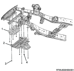
3. Models with front and rear underguards and oil pan guard.
1) Remove the oil pan guard from the frame.
2) Remove the rear underguard from the frame.
3) Remove the front underguard from the frame.
Models with hydraulic power steering
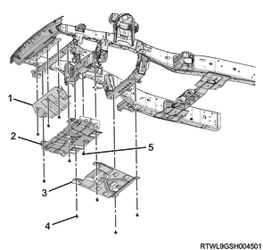
Legend
- Front underguard
- Rear underguard
- Oil pan guard
- Bolt
- Clip
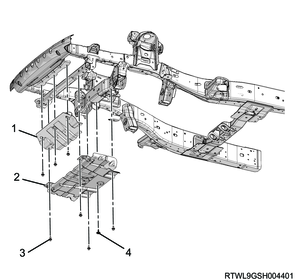
Models with electric power steering
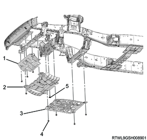
Legend
- Front underguard
- Rear underguard
- Oil pan guard
- Bolt
- Clip
4. Power steering fluid drain
1. Models with hydraulic power steering units
1) Referring to the following, drain the power steering fluid.
Refer to "6.Steering 6B.Power Assisted System power steering fluid replacement".
5. Power steering unit disconnect
1) Remove the cotter pin from the ball joint.
2) Remove the castle nut from the ball joint.
3) Disconnect the tie rod end from the knuckle using the special tool.
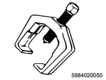
SST: 5-8840-2005-0 - ball joint remover
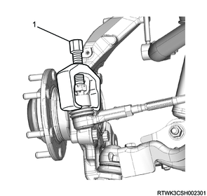
Legend
- 5-8840-2005-0
6. Steering shaft removal
1) Place alignment marks on the lower second steering shaft.
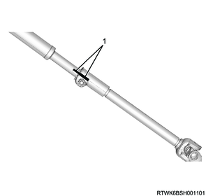
Legend
- Alignment mark
2) Place alignment marks on the universal joint of the lower second steering shaft.
3) Disconnect the universal joint of the lower second steering shaft from the power steering unit.
4) Lock the tilt lever.
5) Remove the lower second steering shaft from the second steering shaft.
Note
- Disconnect the lower second steering shaft at the position shown in the diagram.
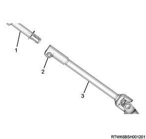
Legend
- Second steering shaft
- Remove the bolt.
- Lower second steering shaft
7. Power steering unit removal
1) For models with electric power steering, disconnect the connector from the electric power steering unit.
2) Remove the power steering unit from the cross member.