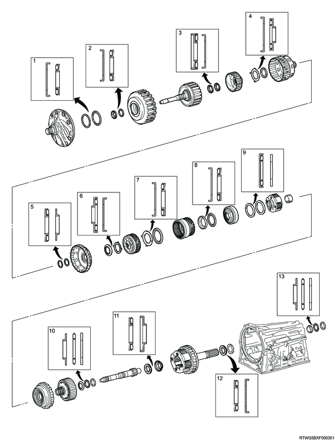
1. Component views
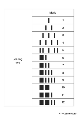
Race and bearing specifications
| Race (Front) |
Bearing |
Race (Rear) |
||||
| Outer diameter |
Inner diameter |
Outer diameter |
Inner diameter |
Outer diameter |
Inner diameter |
|
| 1 |
87.74 mm { 3.4543 in } |
74.2 mm { 2.921 in } |
85.6 mm { 3.370 in } |
71.9 mm { 2.831 in } |
- |
- |
| 2 |
52.8 mm { 2.079 in } |
40.0 mm { 1.575 in } |
52.0 mm { 2.047 in } |
34.6 mm { 1.362 in } |
- |
- |
| 3 |
- |
- |
41.1 mm { 1.618 in } |
21.3 mm { 0.839 in } |
44.8 mm { 1.764 in } |
22.6 mm { 0.890 in } |
| 4 |
56.5 mm { 2.224 in } |
38.40 mm { 1.512 in } |
56.6 mm { 2.228 in } |
33.3 mm { 1.311 in } |
- |
- |
| 5 |
- |
- |
52.8 mm { 2.079 in } |
39.6 mm { 1.559 in } |
52.8 mm { 2.079 in } |
40.83 mm { 1.6075 in } |
| 6 |
- |
- |
61.2 mm { 2.409 in } |
37.1 mm { 1.461 in } |
62.8 mm { 2.472 in } |
44.0 mm { 1.732 in } |
| 7 |
86.3 mm { 3.398 in } |
65.8 mm { 2.591 in } |
78.8 mm { 3.102 in } |
63.3 mm { 2.492 in } |
- |
- |
| 8 |
78.9 mm { 3.106 in } |
66.3 mm { 2.610 in } |
78.8 mm { 3.102 in } |
63.3 mm { 2.492 in } |
- |
- |
| 9 |
- |
- |
76.4 mm { 3.008 in } |
55.7 mm { 2.193 in } |
74.0 mm { 2.913 in } |
53.7 mm { 2.114 in } |
| 10 |
49.0 mm { 1.929 in } |
33.4 mm { 1.315 in } |
49.35 mm { 1.9429 in } |
32.1 mm { 1.264 in } |
49.0 mm { 1.929 in } |
32.1 mm { 1.264 in } |
| 11 |
- |
- |
41.5 mm { 1.634 in } |
21.0 mm { 0.827 in } |
41.5 mm { 1.634 in } |
23.13 mm { 0.9106 in } |
| 12 |
- |
- |
61.0 mm { 2.402 in } |
43.55 mm { 1.7146 in } |
67.1 mm { 2.642 in } |
47.1 mm { 1.854 in } |
| 13 |
51.2 mm { 2.016 in } |
37.0 mm { 1.457 in } |
52.5 mm { 2.067 in } |
36.1 mm { 1.421 in } |
51.0 mm { 2.008 in } |
36.1 mm { 1.421 in } |
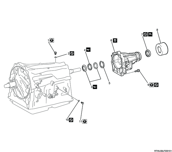
Transmission case
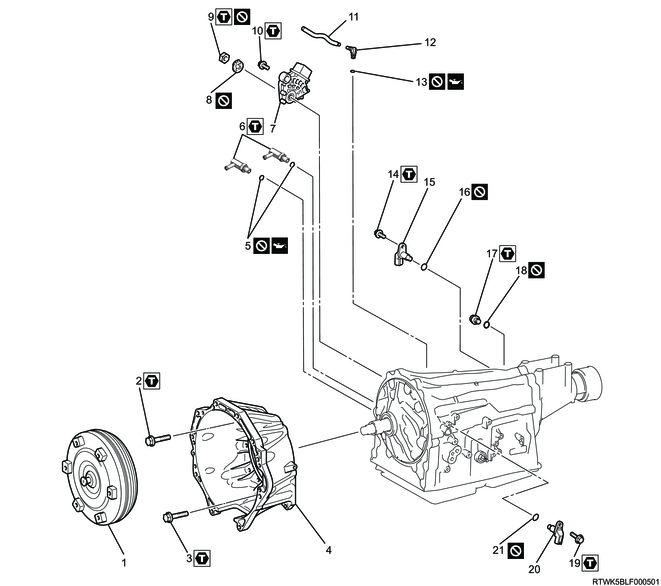
Part name
- Torque converter assembly
- Bolt
- Bolt
- Converter housing
- O-ring
- Elbow
- Inhibitor switch
- Lock washer
- Nut
- Bolt
- Breather hose
- Breather plug
- O-ring
- Bolt
- Output speed sensor
- O-ring
- Filler plug
- O-ring
- Bolt
- Turbine Speed Sensor
- O-ring
Tightening torque
2: 34 N・m { 3.5 kgf・m / 25 lb・ft } M10
3: 57 N・m { 5.8 kgf・m / 42 lb・ft } M12
6: 29 N・m { 3.0 kgf・m / 21 lb・ft }
9: 7 N・m { 0.7 kgf・m / 62 lb・in }
10: 13 N・m { 1.3 kgf・m / 115 lb・in }
14: 5 N・m { 0.5 kgf・m / 44 lb・in }
17: 40 N・m { 4.1 kgf・m / 30 lb・ft }
19: 5 N・m { 0.5 kgf・m / 44 lb・in }
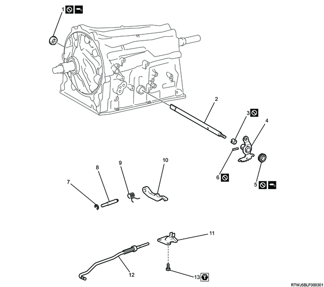
Part name
- Manual shaft oil seal
- Manual valve lever shaft
- Spacer
- Manual valve lever
- Manual shaft oil seal
- Spring pin
- Snap ring
- Parking lock pawl shaft
- Torsion spring
- Parking lock pawl
- Parking lock pawl bracket
- Parking lock rod
- Bolt
Tightening torque
13: 18 N・m { 1.8 kgf・m / 13 lb・ft }
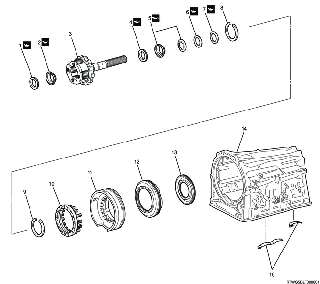
Transmission case adapter (4WD models)
Part name
- Bolt
- O-ring
- Thrust bearing race
- Thrust needle roller bearing
- Snap ring
- Snap ring
- Transmission case adapter bearing
- Transmission case adapter
- Transmission case adapter oil seal
- Bolt
- O-ring
- Bolt
Tightening torque
1: 39 N・m { 4.0 kgf・m / 29 lb・ft }
10: 34 N・m { 3.5 kgf・m / 25 lb・ft }
12: 7 N・m { 0.7 kgf・m / 62 lb・in }
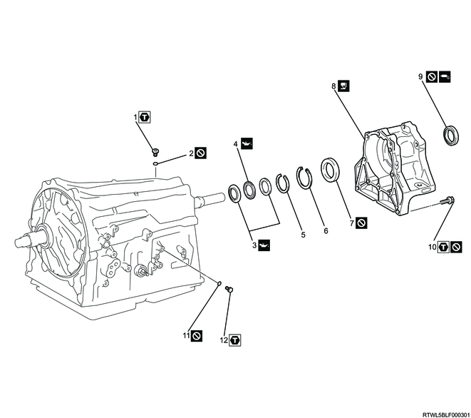
Extension housing (2WD models)
Part name
- Bolt
- O-ring
- Thrust bearing race
- Thrust needle roller bearing
- Snap ring
- Extension housing
- Extension housing oil seal
- Extension housing dust deflector
- Bolt
- O-ring
- Bolt
Tightening torque
1: 39 N・m { 4.0 kgf・m / 29 lb・ft }
9: 34 N・m { 3.5 kgf・m / 25 lb・ft }
11: 7 N・m { 0.7 kgf・m / 62 lb・in }
Valve body assembly
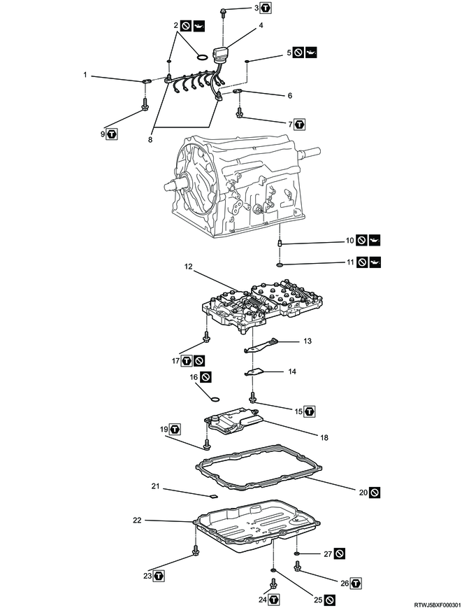
Part name
- Temperature sensor clamp
- O-ring
- Bolt
- Transmission internal harness
- O-ring
- Temperature sensor clamp
- Bolt
- Oil temperature sensor
- Bolt
- Brake drum gasket
- Transmission case gasket
- Valve body assembly
- Detent spring
- Detent spring cover
- Bolt
- O-ring
- Bolt
- Oil strainer
- Bolt
- Oil pan gasket
- Oil cleaner magnet
- Transmission oil pan sub-assembly
- Bolt
- Bolt
- Gasket
- Bolt
- Gasket
Tightening torque
3: 5 N・m { 0.5 kgf・m / 44 lb・in }
7: 10 N・m { 1.0 kgf・m / 89 lb・in }
9: 11 N・m { 1.1 kgf・m / 97 lb・in }
15: 10 N・m { 1.0 kgf・m / 89 lb・in }
17: 11 N・m { 1.1 kgf・m / 97 lb・in }
19: 10 N・m { 1.0 kgf・m / 89 lb・in }
23: 7 N・m { 0.7 kgf・m / 62 lb・in }
24: 20 N・m { 2.0 kgf・m / 15 lb・ft }
26: 20 N・m { 2.0 kgf・m / 15 lb・ft }
Valve body assembly
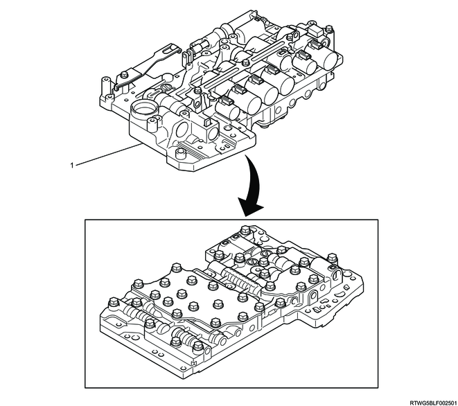
Part name
- Valve body assembly
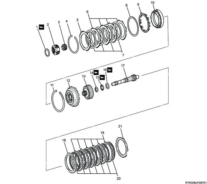
Gear train
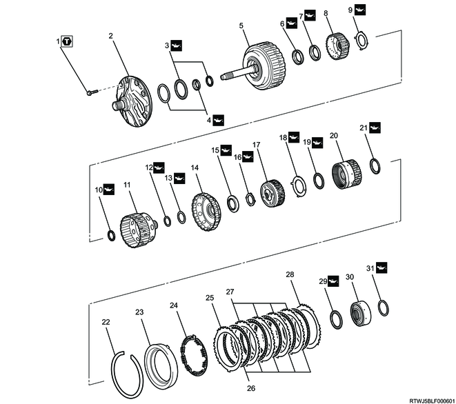
Part name
- Bolt
- Oil pump assembly
- Thrust needle roller bearing
- Thrust bearing race
- Direct clutch assembly and forward clutch assembly
- Thrust needle roller bearing
- Thrust bearing race
- Forward clutch hub
- Thrust bearing race
- Thrust needle roller bearing
- Clutch hub sub-assembly
- Thrust needle roller bearing with race
- Thrust bearing race
- Sun gear input drum
- Thrust needle roller bearing with race
- Thrust bearing race
- Front planetary gear assembly
- Thrust bearing race
- Thrust needle roller bearing with race
- Front planetary ring gear with front planetary ring gear flange sub-assembly
- Thrust bearing race
- Snap ring
- Brake cylinder No. 2 with brake piston No. 2
- Brake piston return spring sub-assembly No. 2
- Brake flange No. 2
- Brake disc No. 2
- Brake plate No. 2
- Brake flange No. 2
- Thrust needle roller bearing with race
- Middle planetary ring gear flange with middle planetary ring gear
- Thrust needle roller bearing
Tightening torque
1: 21 N・m { 2.1 kgf・m / 15 lb・ft }
Part name
- Thrust bearing race
- Middle planetary gear assembly
- Planetary sun gear
- Snap ring
- Brake flange No. 1
- Brake plate No. 1
- Brake disc No. 1
- Snap ring
- Brake piston return spring sub-assembly
- Brake cylinder No. 1 with brake piston No. 1
- Snap ring
- 1 way clutch assembly No. 3 with inner race
- Rear planetary ring gear flange sub-assembly
- Thrust bearing race
- Thrust needle roller bearing
- Thrust bearing race
- Intermediate shaft
- Brake flange No. 4
- Brake plate No. 4
- Brake disc No. 4
- Brake flange No. 4
Part name
- Thrust needle roller bearing with race
- Thrust bearing race
- Rear planetary gear assembly
- Thrust needle roller bearing with race
- Thrust bearing race
- Thrust needle roller bearing
- Thrust bearing race
- Snap ring
- Snap ring
- 1st and reverse brake return spring sub-assembly
- 1st and reverse brake piston
- Brake reaction sleeve
- Inner brake piston No. 4
- Transmission case
- Brake plate stopper spring
2. Plate stopper spring installation
1) Coat the bearing on the differential case with ATF.
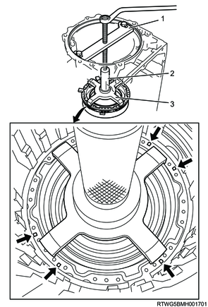
2) Install the 2 brake plate stopper springs to the transmission case.
3. Brake reaction sleeve installation
1) Coat the new 2 O-rings and inner brake piston No. 4 with ATF.
Caution
- Do not reuse the O-ring.
2) Install them to inner brake piston No. 4.
| Inner diameter |
Thickness |
| 67.35 mm { 2.6516 in } |
2.62 mm { 0.1031 in } |
| 105.55 mm { 4.1555 in } |
2.62 mm { 0.1031 in } |
3) Coat the new 2 O-rings with ATF.
Caution
- Do not reuse the O-ring.
4) Install them to the brake reaction sleeve.
| Inner diameter |
Thickness |
| 79.1 mm { 3.1142 in } |
2.62 mm { 0.1031 in } |
| 112.7 mm { 4.4370 in } |
2.62 mm { 0.1031 in } |
5) Coat the sliding surface of the transmission case and the brake reaction sleeve and inner brake piston No. 4 with ATF.
6) Install inner brake piston No. 4 to the brake reaction sleeve.
Caution
- Be careful not to damage the O-rings.
7) With inner brake piston No. 4 underneath (the rear side), install the brake reaction sleeve and brake piston No. 4 to the transmission case.
Caution
- Be careful not to damage the O-rings and the sliding surface of the transmission case.

4. 1st and reverse brake piston installation
1) Coat the new O-ring and the 1st and reverse brake piston with ATF.
Caution
- Do not reuse the O-ring.
2) Install it to the 1st and reverse brake piston.
| Inner diameter |
Thickness |
| 131.6 mm { 5.1811 in } |
2.62 mm { 0.1031 in } |

3) Install the 1st and reverse brake piston to the transmission case while making sure that the protrusion of the 1st and reverse brake piston is positioned as shown in the figure.
Caution
- Be careful not to damage the O-ring.
4) Install the 1st and reverse brake piston return spring sub-assembly to the transmission case.
Note
- Place the 1st and reverse brake return spring sub-assembly onto the 1st and reverse brake piston.
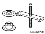
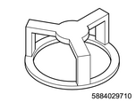
5) Set the special tool on the 1st and reverse brake piston return spring sub-assembly, tighten the special tool and compress the 1st and reverse brake piston return spring sub-assembly.
Caution
- Be careful not to shorten the return spring too much.
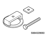
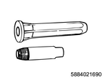
SST: 5-8840-2966-0 - spring compressor
6) Using snap ring pliers, install the snap ring in the groove.
Caution
- Be careful not to expand the snap ring too much.
Legend
- 5-8840-2966-0
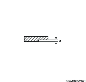
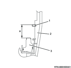
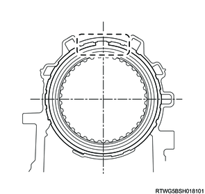
5. Brake disc No.4 adjustment
1) Make sure that the 1st and reverse brake piston is pushed fully into the case.
2) Using vernier calipers, measure as shown in the illustration.
Caution
- Measure the circumference of the 1st and reverse brake piston at three places, and make sure that the average value is within the specified range.
- If the average value is outside the specified range, reinstall the 1st and reverse brake piston, brake reaction sleeve, and inner brake piston.
Standard: 32.07 to 32.81 mm { 1.2626 to 1.2917 in } Length A
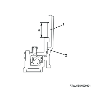
Legend
- Transmission case
- 1st and reverse brake piston
Standard value
a: 32.07 to 32.81 mm { 1.2626 to 1.2917 in } Length A
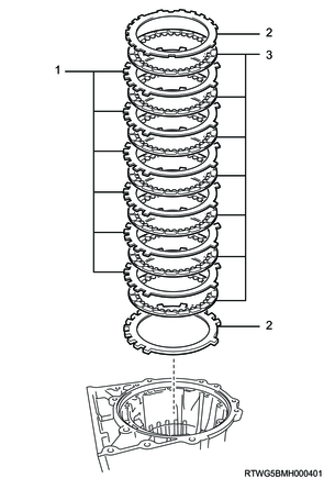
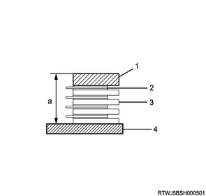
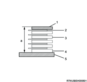
3) Stack the 7 discs and the 6 plates on top of the surface plate as shown in the illustration.
Note
- Check the number and order of discs and plates.
4) With the disc pressed against the surface plate, measure as shown in the illustration using vernier calipers.
Check the measurement load.
3.92 to 4.9 N {0.40 to 0.50 kg / 0.88 to 1.10 lb}
Caution
- Measure the facing of the disc at three places, and make sure that the average value is within the specified range.
Standard: 29.94 to 30.96 mm { 1.1787 to 1.2189 in } Length B
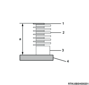
Legend
- Disc (7 pieces)
- Plate (6 pieces)
- Flange
- Surface plate
Standard value
a: 29.94 to 30.96 mm { 1.1787 to 1.2189 in } Length B
5) Using vernier calipers, measure brake flange No. 4 as shown in the illustration.
Note
- Brake flange No. 4 comes in 11 types.
Standard: 0.00 to 1.43 mm { 0.0000 to 0.0563 in } Length C
Standard value
a: 0.00 to 1.43 mm { 0.0000 to 0.0563 in } Length C
6) Calculate the pack clearance from the measured value and the disc distortion compensation value (0.41 mm {0.0161 in}).
Standard: 0.7 to 1.0 mm { 0.0276 to 0.0394 in } Pack clearance
No. 4 brake pack clearance = Length A - Length B - Length C - 0.41 mm {0.0161 in}
Caution
- If the No. 4 brake pack clearance is not as specified, select an appropriate brake flange No. 4.
| Mark |
Thickness |
| 0 |
0 mm { 0 in } |
| 1 |
0.17 mm { 0.0067 in } |
| 3 |
0.31 mm { 0.0122 in } |
| 4 |
0.45 mm { 0.0177 in } |
| 5 |
0.59 mm { 0.0232 in } |
| 7 |
0.73 mm { 0.0287 in } |
| 8 |
0.87 mm { 0.0343 in } |
| 10 |
1.01 mm { 0.0398 in } |
| 11 |
1.15 mm { 0.0453 in } |
| 12 |
1.29 mm { 0.0508 in } |
| 14 |
1.43 mm { 0.0563 in } |
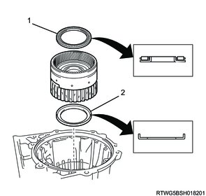
6. Rear planetary gear assembly installation
1) Coat the thrust bearing race with ATF and install it to the transmission case.
2) Coat the 2 thrust needle roller bearings with races and thrust bearing races with ATF and install them to the rear planetary gear assembly.
3) Install the rear planetary gear assembly to the transmission case.
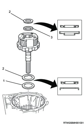
Legend
- Thrust bearing race
- Thrust needle roller bearing with race
- Thrust bearing race
4) Coat the thrust needle roller bearing and 2 thrust bearing races with ATF and install them to the rear planetary gear assembly.

5) Using snap ring pliers, install the snap ring to the rear planetary gear assembly.

7. Rear planetary gear assembly adjustment
1. 2WD models
1) Using a feeler gauge, measure the clearance between the snap ring and the thrust bearing race.
Caution
- If the output shaft end play is not as specified, select an appropriate thrust bearing race.
Standard: 0.02 to 0.12 mm { 0.0008 to 0.0047 in }
Thrust bearing race size
Legend
- 3.80 mm {0.1496 in}
- 3.85 mm {0.1516 in}
- 3.90 mm {0.1535 in}
- 3.95 mm {0.1555 in}
- 4.00 mm {0.1575 in}
- 4.05 mm {0.1594 in}
- 4.10 mm {0.1614 in}
- 4.15 mm {0.1634 in}
- 4.20 mm {0.1654 in}
- 4.25 mm {0.1673 in}
- 4.30 mm {0.1693 in}
- 4.35 mm {0.1713 in}
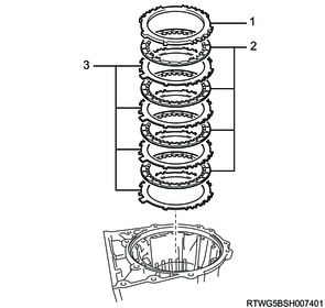
8. Brake disc No.4 installation
1) Install the 2 flanges, 7 discs and 6 plates to the transmission case as shown in the figure.
Note
- Check the number and order of flange, discs and plates.
Legend
- Plate
- Flange
- Disc
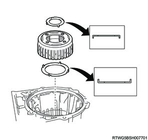
9. Rear planetary ring gear installation
1) Coat the thrust needle roller bearing and thrust bearing race with ATF and install them to the intermediate shaft.
2) Install the intermediate shaft to the transmission case.
3) Coat the thrust bearing race with ATF and install it to the rear planetary ring gear flange with the rear planetary ring gear.
4) Install the rear planetary ring gear flange with rear planetary ring gear to the transmission case.
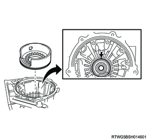
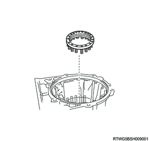
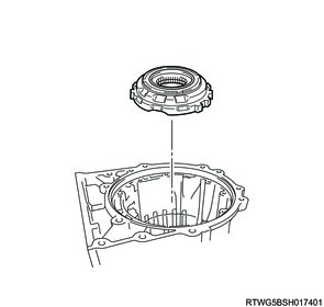
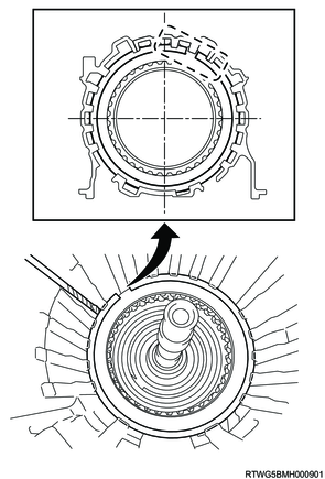
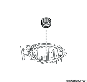
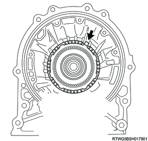
10. 1way clutch No.3 installation
1) Coat the 1 way clutch inner race and the 1 way clutch assembly No. 3 with ATF.
2) Install it to 1 way clutch assembly No. 3.
Note
- Rotate the 1 way clutch inner race clockwise to install it.
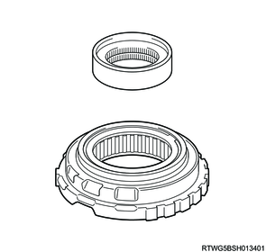
3) Install 1 way clutch assembly No. 3 with the 1 way clutch inner race to the transmission case.
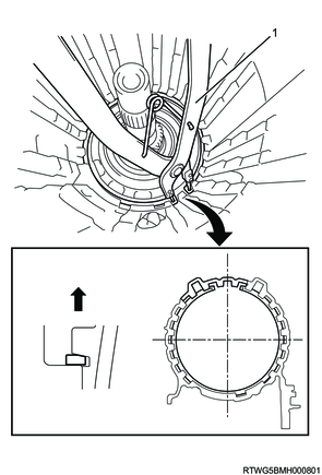
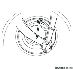
4) Using the special tool, install the snap ring to the transmission case.
Caution
- Install the snap ring so that the tapered side is facing out.
- Be sure to install the snap ring so that the ends of the snap ring are within the area shown in the figure.
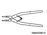
SST: 5-8840-2961-0 - snap ring pliers
Legend
- 5-8840-2961-0
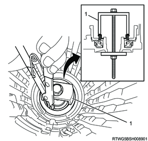
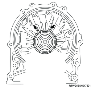
11. Brake piston No.1 installation
1) Install brake cylinder No. 1 with brake piston No. 1 to the transmission case while making sure that the 2 claws of brake cylinder No. 1 with brake piston No. 1 are positioned as shown in the figure.

2) Align the 2 claws of brake piston return spring sub-assembly No. 1 with the 2 claws of brake cylinder No. 1, and then install the brake piston return spring sub-assembly No. 1 to brake piston No. 1.
3) Place the special tool on brake piston return spring sub-assembly No. 1, and compress the brake piston return spring sub-assembly No. 1 with a shop press.
Note
- Place the special tool on the surface with protrusions.
Caution
- Be careful not to shorten the return spring too much.
SST: 5-8840-2973-0 - spring compressor kit
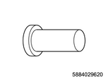
SST: 5-8840-2962-0 - oil seal installer
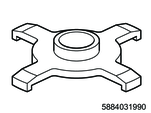
SST: 5-8840-3199-0 - spring compressor
Legend
- 5-8840-2973-0
- 5-8840-2962-0
- 5-8840-3199-0
4) Using a screwdriver, install the snap ring to the transmission case.
Caution
- Be careful not to damage the transmission case.
- Be sure to install the snap ring so that the ends of the snap ring are within the area shown in the figure.

12. Brake disc No.1 adjustment
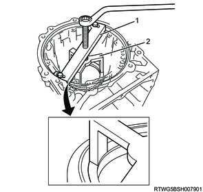
1) Install the snap ring to the transmission case.
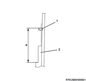
2) With the snap ring pulled up on the converter housing side, measure as shown in the illustration using vernier calipers.
Standard: 26.27 to 26.99 mm { 1.0342 to 1.0626 in } Length A
Caution
- Measure the circumference of the transmission case at three places, and make sure that the average value is within the specified range.
- If the average value is outside the specified range, reinstall brake cylinder No. 1 with brake piston No. 1.
Legend
- Snap ring
- Transmission case
- Brake cylinder No. 1
Standard value
a: 26.27 to 26.99 mm { 1.0342 to 1.0626 in } Length A
3) Stack the flange, the 4 discs, and the 4 plates on top of the surface plate as shown in the illustration.
Note
- When not replacing the disc and plate, use the installed flange.
- When using a new disc and plate, use a 5.3 mm {0.2087 in} flange.
- Check the number and order of flange, discs and plates.
4) With the flange pressed against the surface plate, measure as shown in the illustration using vernier calipers.
Check the measurement load.
3.92 to 4.9 N {0.40 to 0.50 kg / 0.88 to 1.10 lb}
Caution
- Measure the circumference of the flange at three places, and make sure that the average value is within the specified range.
Standard: 22.43 to 23.00 mm { 0.8831 to 0.9055 in } Length B
Legend
- Flange (1 piece)
- Disc (4 pieces)
- Plate (4 pieces)
- Surface plate
Standard value
a: 22.43 to 23.00 mm { 0.8831 to 0.9055 in } Length B
5) Calculate the pack clearance from the measured value, the disc distortion compensation value 0.24 mm {0.009 in}, and the snap ring thickness 3.0 mm {0.118 in}.
Standard: 0.40 to 0.70 mm { 0.0157 to 0.0276 in } Pack clearance
No. 1 brake pack clearance = Length A - Length B - 0.24 mm {0.009 in} - 3.0 mm {0.118 in}
Caution
- If the No. 1 brake pack clearance is not as specified, select an appropriate brake flange No. 1.
| Mark |
Thickness |
| 0 |
4.9 mm { 0.1929 in } |
| 1 |
5.0 mm { 0.1969 in } |
| 2 |
5.1 mm { 0.2008 in } |
| 3 |
5.2 mm { 0.2047 in } |
| 4 |
5.3 mm { 0.2087 in } |
| 5 |
5.4 mm { 0.2126 in } |
| 6 |
5.5 mm { 0.2165 in } |
| 7 |
5.6 mm { 0.2205 in } |
| 8 |
5.7 mm { 0.2244 in } |
| A |
5.8 mm { 0.2283 in } |
13. Brake disc No.1 installation
1) Install the flange, 4 discs and 4 plates to the transmission case as shown in the figure.
Note
- Check the number and order of flange, discs and plates.
Legend
- Flange
- Disc
- Plate
2) Using a screwdriver, install the snap ring to the transmission case.
Caution
- Be careful not to damage the transmission case.
- Be sure to install the snap ring so that the ends of the snap ring are within the area shown in the figure.
14. Planetary sun gear installation
1) Install the planetary sun gear to the transmission case.
15. Middle planetary gear assembly installation
1) Coat the thrust bearing race with ATF and install it to the middle planetary gear assembly.
2) Install the middle planetary gear assembly to the transmission case.

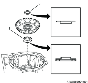
16. Middle planetary ring gear installation
1) Coat the thrust needle roller bearing and thrust needle roller bearing with race with ATF and install them to the middle planetary ring gear flange with middle planetary ring gear.
2) Install the middle planetary ring gear flange with the middle planetary ring gear to the transmission case.

Legend
- Thrust needle roller bearing
- Thrust needle roller bearing with race
17. Brake disc No.2 adjustment
1) Install the snap ring to the transmission case.
2) With the snap ring pulled up on the converter housing side, measure as shown in the illustration using vernier calipers.
Note
- Measure 3 locations and use the average value.
Caution
- Be careful not to expand the snap ring too much.
Standard: 59.72 to 59.88 mm { 2.3512 to 2.3575 in } Length A
Legend
- Snap ring
- Transmission case
Standard value
a: 59.72 to 59.88 mm { 2.3512 to 2.3575 in } Length A
3) Make sure that brake piston No. 2 is pushed fully into brake cylinder No. 2.
4) Using vernier calipers, measure as shown in the illustration.
Standard: 28.22 to 28.54 mm { 1.1110 to 1.1236 in } Length B
Caution
- Measure the circumference of brake cylinder No. 2 with brake piston No. 2 at three places, and make sure that the average value is within the specified range.
- If the average value is outside the specified range, reinstall brake cylinder No. 2 with brake piston No. 2.
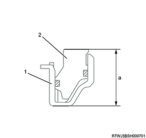
Legend
- Brake cylinder No. 2
- Brake piston No. 2
Standard value
a: 28.22 to 28.54 mm { 1.1110 to 1.1236 in } Length B
5) Stack the flange, the 5 discs, and the 5 plates on top of the surface plate as shown in the illustration.
Note
- When not replacing the disc and plate, use the installed flange.
- When using a new disc and plate, use a 2.4 mm {0.0945 in} flange.
- Check the number and order of flange, discs and plates.
6) With the flange pressed against the surface plate, measure as shown in the illustration using vernier calipers.
Check the measurement load.
3.92 to 4.9 N {0.40 to 0.50 kg / 0.88 to 1.10 lb}
Caution
- Measure the circumference of the flange at three places, and make sure that the average value is within the specified range.
Standard: 26.06 to 26.71 mm { 1.0260 to 1.0516 in } Length C
Legend
- Flange for adjustment (1 piece)
- Disc (5 pieces)
- Plate (4 pieces)
- Flange (1 piece)
- Surface plate
Standard value
a: 26.06 to 26.71 mm { 1.0260 to 1.0516 in } Length C
7) Calculate the pack clearance from the measured value, the disc distortion compensation value 0.37 mm {0.0146 in}, and the snap ring thickness 4.0 mm {0.1575 in}.
Standard: 0.50 to 0.80 mm { 0.0197 to 0.0315 in } Pack clearance
No. 2 brake pack Clearance = Length A - Length B - Length C - 0.37 mm {0.0146 in} - 4.0 mm {0.1575 in}
Caution
- If the No. 2 brake pack clearance is not as specified, select an appropriate brake flange No. 2.
| Mark |
Thickness |
| 0 |
2.0 mm { 0.0787 in } |
| 1 |
2.1 mm { 0.0827 in } |
| 2 |
2.2 mm { 0.0866 in } |
| 3 |
2.3 mm { 0.0906 in } |
| 4 |
2.4 mm { 0.0945 in } |
| 5 |
2.5 mm { 0.0984 in } |
| 6 |
2.6 mm { 0.1024 in } |
| 7 |
2.7 mm { 0.1063 in } |
| 8 |
2.8 mm { 0.1102 in } |
18. Brake disc No.2 installation
1) Install the 4 plates, 5 discs and the 2 flanges to the transmission case as shown in the figure.
Note
- Check the number and order of flange, discs and plates.

Legend
- Plate
- Flange
- Disc
19. Brake piston No.2 installation
1) Install brake piston return spring sub-assembly No. 2 to the transmission case while making sure that the claw of the brake piston return spring sub-assembly is positioned as shown in the figure.
2) Install brake cylinder No. 2 with brake piston No. 2 to the transmission case while making sure that the claw of brake cylinder No. 2 with brake piston No. 2 is positioned as shown in the figure.
Note
- Align the brake piston No. 2 oil hole and the transmission case oil hole.
Legend
- Oil hole
3) Place the special tool on brake cylinder No. 2 with brake piston No. 2, and compress the brake piston return spring sub-assembly with a shop press.
Caution
- Be careful not to shorten the return spring too much.
- Be careful not to damage brake cylinder No. 2.
SST: 5-8840-2971-0 - spring compressor
SST: 5-8840-2973-0 - spring compressor kit
Legend
- 5-8840-2973-0
- 5-8840-2971-0
4) Using a screwdriver, install the snap ring to the transmission case.
Caution
- Be careful not to damage the transmission case.
- Be sure to install the snap ring so that the ends of the snap ring are within the area shown in the figure.
20. Front planetary ring gear installation
1) Coat the thrust needle roller bearing with race and thrust bearing race with ATF and install them to the front planetary ring gear with front planetary ring gear flange sub-assembly.
2) Install the front planetary ring gear with front planetary ring gear flange sub-assembly to the transmission case.
Legend
- Thrust needle roller bearing with race
- Thrust bearing race
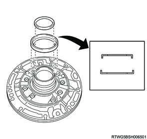
21. Front planetary gear assembly installation
1) Coat the 2 thrust bearing races with ATF and install them to the front planetary gear assembly.
2) Install the front planetary gear assembly to the transmission case.
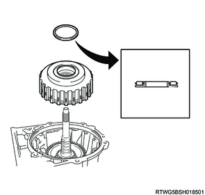
22. Sun gear input drum installation
1) Coat the thrust needle roller bearing with race and thrust bearing race with ATF and install them to the sun gear input drum.
2) Install the sun gear input drum to the transmission case.
Legend
- Thrust needle roller bearing with race
- Thrust bearing race
23. Forward clutch assembly installation
1) Coat the 2 thrust needle roller bearings with ATF and install them to the forward clutch hub sub-assembly.
2) Install the clutch hub sub-assembly to the transmission case.
3) Coat the 2 thrust bearing races with ATF and install them to the forward clutch hub.
4) Install the forward clutch hub to the transmission case.

5) Coat the 2 thrust needle roller bearings with races with ATF and install them to the forward clutch assembly (input shaft).
6) Install the forward clutch assembly (input shaft) to the transmission case.
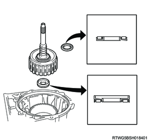
7) Coat the thrust needle roller bearing with race with ATF and install it to the direct clutch assembly.
8) Install the direct clutch assembly to the transmission case.
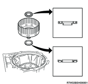
24. Oil pump installation
1) Coat the 2 thrust bearing races with ATF and install them to the oil pump assembly.
2) Set the oil pump assembly on the C-2 clutch drum sub-assembly, and align the bolt holes of the oil pump assembly with the transmission case.
Caution
- Be careful not to damage the seal rings and transaxle oil seal ring.
3) Temporarily install the oil pump assembly to the transmission case.
4) Install the oil pump assembly with the 10 bolts.
Tightening torque: 21 N・m { 2.1 kgf・m / 15 lb・ft }
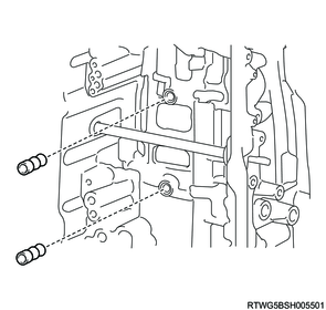
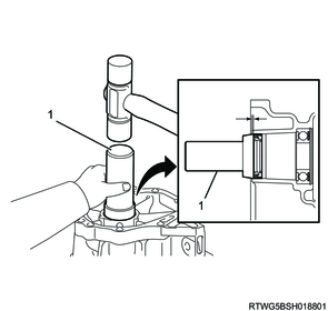
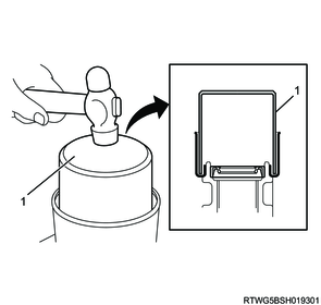
25. Manual shaft oil seal installation
1) Coat the lip of the 2 new manual shaft oil seals with grease.
Caution
- Do not reuse the oil seal.
2) Using the special tool and a hammer, install the 2 new manual shaft oil seals to the transmission case.
-0.5 to 0.5 mm { -0.020 to 0.020 in } Press-fitting depth (From the end of the transmission case)
Caution
- Be careful not to damage the manual valve lever shaft oil seal.
- Be careful not to damage the transmission case.
- Be careful not to damage the manual valve lever shaft.
SST: 5-8840-2169-0 - oil seal installer
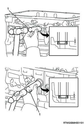
Legend
- 5-8840-2169-0
26. Manual valve lever installation
1) Install a new spacer to the manual valve lever.
Caution
- Do not reuse the spacer.
2) Install the manual valve lever shaft to the transmission case through the manual valve lever.
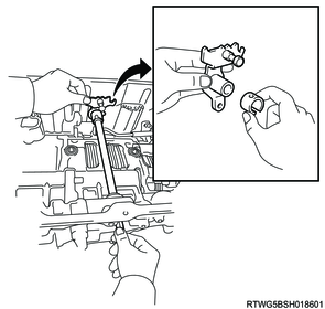
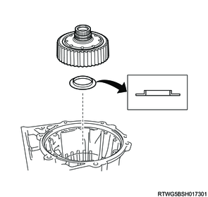
3) Using a pin punch (3 mm {0.118 in}) and hammer, tap in a new spring pin.
Caution
- Do not reuse the spring pin.
4) Align the manual valve lever indentation with the spacer hole, and stake them together with a punch.
5) Make sure that the shaft rotates smoothly.

Legend
- Spring pin
27. Parking lock pawl shaft installation
1) Install the snap ring to the parking lock pawl shaft.
2) Install the parking lock pawl and the parking lock pawl shaft to the transmission case.
3) Install the torsion spring to the parking lock pawl shaft.
Caution
- Be careful not to apply too much force to the spring.

28. Parking lock rod installation
1) Connect the parking lock rod to the manual valve lever.

29. Parking lock pawl bracket installation
1) Place the parking lock pawl bracket and parking lock pawl onto the transmission case.
2) Install the 3 bolts.
Tightening torque: 18 N・m { 1.8 kgf・m / 13 lb・ft }
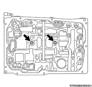
30. Brake drum gasket installation
1) Coat the 2 new brake drum gaskets with ATF.
Caution
- Do not reuse the gasket.
2) Install 2 new brake drum gaskets to the transmission case.
Note
- Install the brake drum gasket metal side facing outward.
3) Coat the 2 new transmission case gaskets with ATF.
Caution
- Do not reuse the gasket.
4) Install 2 new transmission case gaskets to the transmission case.
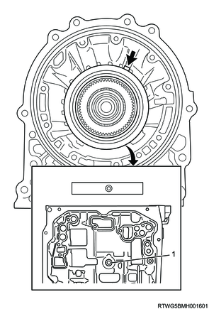
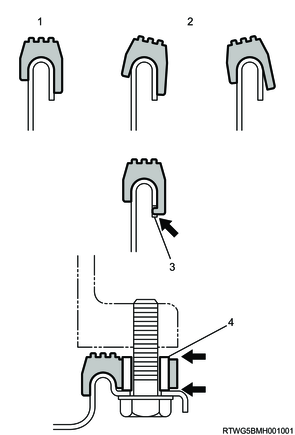
31. Valve body assembly installation
1) Insert the manual valve lever into the groove on the end of the manual valve.
2) Install the valve body assembly with the new 12 bolts to the transmission case.
Caution
- Do not reuse the bolt.
Tightening torque: 11 N・m { 1.1 kgf・m / 97 lb・in }
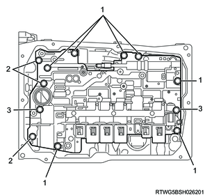
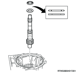
Legend
- M6 x 1.0 x 25 mm
- M6 x 1.0 x 36 mm
- M6 x 1.0 x 50 mm
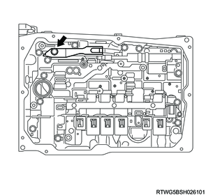
32. Detent spring installation
1) Install the detent spring and detent spring cover with the bolt to the transmission case.
Caution
- Make sure to align the center of the detent spring roller with the center of the manual valve lever.
Tightening torque: 10 N・m { 1.0 kgf・m / 89 lb・in }
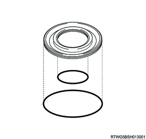
33. Oil strainer installation
1) Coat a new O-ring with ATF, and install it to the oil strainer.
Caution
- Do not reuse the O-ring.
| Inner diameter |
Thickness |
| 27.73 mm { 1.0917 in } |
2.62 mm { 0.1031 in } |
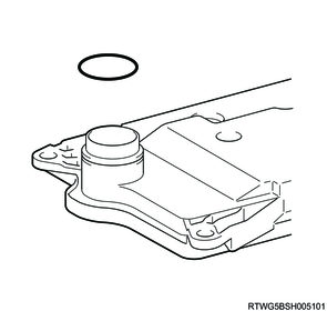
2) Install the oil strainer with the 3 bolts to the valve body assembly.
Tightening torque: 10 N・m { 1.0 kgf・m / 89 lb・in }
34. Transmission internal harness installation
1) Coat a new O-ring with ATF, and install it to the transmission wire.
Caution
- Do not reuse the O-ring.
| Inner diameter |
Thickness |
| 36.8 mm { 1.4488 in } |
2.4 mm { 0.0945 in } |
2) Install the transmission wire to the transmission case with the bolt.
Tightening torque: 5 N・m { 0.5 kgf・m / 44 lb・in }

3) Connect the 8 solenoid connectors.
4) Install the 2 oil temperature sensors (OT1, OT2) and 2 temperature sensor clamps to the valve body assembly with the 2 bolts.
Tightening torque: 10 N・m { 1.0 kgf・m / 89 lb・in } M6 x 1.0 x 14 mm
Tightening torque: 11 N・m { 1.1 kgf・m / 97 lb・in } M6 x 1.0 x 36 mm
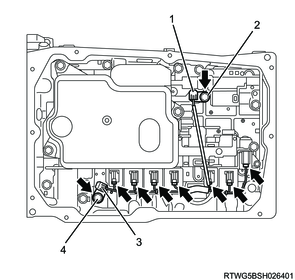
Legend
- Temperature sensor (OT1)
- M6 x 1.0 x 14 mm
- Temperature sensor (OT2)
- M6 x 1.0 x 36 mm
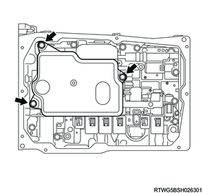
35. Oil pan installation
1) Clean the transmission oil pan sub-assembly.
2) Install the 4 oil cleaner magnets to the transmission oil pan sub-assembly.
Note
- Clean the oil cleaner magnet before installing it.

3) Clean oil off the oil pan gasket fitting surface of the transmission case and the 10 bolt holes.
Note
- Completely remove oil with white gasoline or similar.
4) Install a new oil pan gasket and the transmission oil pan sub-assembly to the transmission case.
Caution
- Do not reuse the oil pan gasket.
- Be careful not to damage the fitting surfaces of the transmission case and the transmission oil pan sub-assembly.
- Be careful not to deform the transmission oil pan sub-assembly.
Legend
- Correct
- Incorrect
- Protrusion
- Sleeve
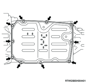
5) Install the 10 bolts to the transmission case.
Caution
- Make sure that there is no oil or foreign matter on the oil pan gasket seal surface and transmission oil pan sub-assembly contact surface.
- Install the oil pan gasket so that there is no slack in the oil pan gasket, and that the seal surface's entire circumference is level.
- Make sure that the oil pan gasket drop prevention protrusions are set on the transmission oil pan sub-assembly.
- When tightening the transmission oil pan sub-assembly, make sure that the oil pan gasket is not pinched between the oil pan gasket tightening area's sleeve and the transmission case seal surface.
Tightening torque: 7 N・m { 0.7 kgf・m / 62 lb・in }
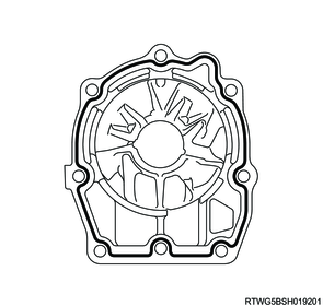
36. Converter housing installation
1) Clean sealant and oil off the converter housing contact surface of the transmission case and the 12 bolt holes.
Note
- Completely remove sealant and oil with white gasoline or similar.
2) Install the converter housing to the transmission case.
Note
- Hit all around the contact surface with a plastic hammer during installation.
Caution
- Be careful not to damage the fitting surface of the converter housing and the transmission case.
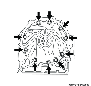
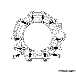
3) Temporarily tighten the 12 bolts by hand as shown in the figure.
Note
- The number shown in the figure indicates the kind of bolts.

Legend
- M10 x 1.5 x 35 mm
- M10 x 1.5 x 35 mm (Seal bolt)
- M12 x 1.75 x 38 mm (Seal bolt)
4) Tighten the 12 bolts in the order shown in the figure.
Caution
- Be sure to tighten bolts (M10 x 1.5 x 35 mm) before tightening bolts (M10 x 1.5 x 35 mm (Seal bolt)) and (M12 x 1.75 x 38 mm (Seal bolt)).
- Be sure to tighten bolts (M10 x 1.5 x 35 mm) evenly and gradually, in a diagonally opposing sequence.
Tightening torque: 34 N・m { 3.5 kgf・m / 25 lb・ft } M10 bolt
Tightening torque: 57 N・m { 5.8 kgf・m / 42 lb・ft } M12 bolt
37. Adapter housing bearing installation
1. 4WD models
1) Using special tool and a press, install the new transmission case adapter bearing to the transmission case adapter.
Note
- Use driver tool set No. 70.
- Face the surface that the balls can be seen towards the case side and install.
- Press-fit the adapter housing bearing until it makes contact with the transmission case adapter.
Caution
- Do not reuse the adapter housing bearing.
- Be careful not to damage the transmission case adapter.
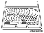
SST: 5-8840-2863-0 - driver tool set

Legend
- 5-8840-2863-0
2) Using snap ring pliers, install the snap ring to the transmission case adapter.
Caution
- Be careful not to damage the transmission case adapter.
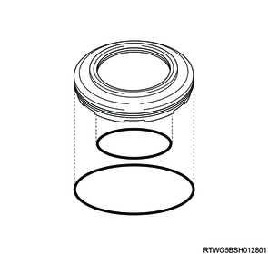
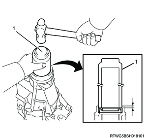
38. Rear oil seal installation
1. 4WD models
1) Coat the lip of the new transmission case adapter oil seal with grease.
Caution
- Do not reuse the oil seal.
2) Using the special tool and a hammer, install the new transmission case adapter oil seal to the transmission case adapter.
1.5 to 2.5 mm { 0.059 to 0.098 in } Press-fitting depth (From the end of the transmission case adapter)
Caution
- Be careful not to damage the transmission case adapter oil seal.
- Be careful not to damage the transmission case adapter.
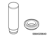
SST: 5-8840-2964-0 - oil seal installer
Legend
- 5-8840-2964-0
2. 2WD models
1) Coat the lip of the new extension housing oil seal with grease.
Caution
- Do not reuse the oil seal.
2) Using the special tool and a hammer, install the new extension housing oil seal to the extension housing.
5.4 to 5.8 mm { 0.213 to 0.228 in } Press-fitting depth (From the end of the extension housing)
Caution
- Be careful not to damage the extension housing oil seal.
- Be careful not to damage the extension housing.
SST: 5-8840-2964-0 - oil seal installer
Legend
- 5-8840-2964-0
39. Adapter housing installation
1. 4WD models
1) Clean sealant and oil off the transmission case adapter contact surface of the transmission case and the 10 bolt holes.
Note
- Completely remove sealant and oil with white gasoline or similar.
2) Apply formed in place gasket to the transmission case adapter as shown in the figure.
Note
- Spread formed in place gasket over the contact surface.

3) Install the transmission case adapter with the new 10 bolts to the transmission case.
Caution
- Do not reuse the bolt.
Tightening torque: 34 N・m { 3.5 kgf・m / 25 lb・ft }

40. Extension housing assembly installation
1. 2WD models
1) Clean sealant and oil off the extension housing contact surface of the transmission case and the 8 bolt holes.
Note
- Completely remove sealant and oil with white gasoline or similar.
2) Apply formed in place gasket to the extension housing in the figure.
Note
- Spread formed in place gasket over the contact surface.
3) Install the extension housing with the new 8 seal bolts to the transmission case.
Caution
- Do not reuse the bolt.
Tightening torque: 34 N・m { 3.5 kgf・m / 25 lb・ft }

Legend
- M10 x 1.5 x 45 mm (Seal bolt)
- M10 x 1.5 x 40 mm (Seal bolt)
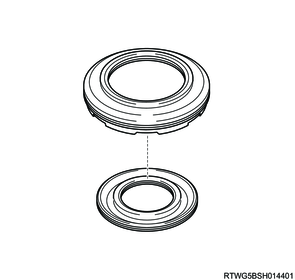
41. Deflector installation
1. 2WD models
1) Using a plastic hammer, install the extension housing dust deflector to the extension housing.
Note
- Press-fit the deflector until it makes contact with the extension housing.
Caution
- Be careful not to damage the extension housing oil seal.
- Be careful not to deform the extension housing.
SST: 5-8840-2965-0 - deflector installer
Legend
- 5-8840-2965-0
42. Elbow installation
1) Coat the 2 new O-rings with ATF, and install them to the 2 elbows.
Caution
- Do not reuse the O-ring.
| Inner diameter |
Thickness |
| 11.68 mm { 0.4598 in } |
1.98 mm { 0.0780 in } |
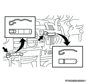
2) Install the 2 elbows to the transmission case.
Caution
- The installation angle of the elbow should be as shown in the diagram.
Tightening torque: 29 N・m { 3.0 kgf・m / 21 lb・ft }
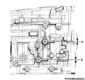
Standard value
a: -2 to 2 °
b: -2 to 2 °
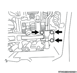
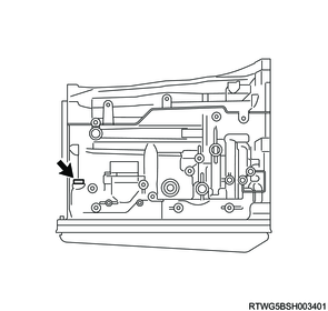
43. Test plug installation
1) Coat the 6 new O-rings with ATF, and install them to the 6 test plugs.
Caution
- Do not reuse the O-ring.
| Inner diameter |
Thickness |
| 6.07 mm { 0.2390 in } |
1.78 mm { 0.0701 in } |
2) Install the 6 test plugs to the transmission case.
Tightening torque: 7 N・m { 0.7 kgf・m / 62 lb・in }

44. Transmission case plug installation
1) Coat a new O-ring with ATF, and install it to the transmission case plug.
Caution
- Do not reuse the O-ring.
| Inner diameter |
Thickness |
| 11.68 mm { 0.4598 in } |
1.98 mm { 0.0780 in } |
2) Using a torx wrench (T55), install the transmission case plug to the transmission case.
Tightening torque: 39 N・m { 4.0 kgf・m / 29 lb・ft }
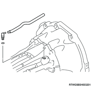
45. Breather hose installation
1) Coat a new O-ring with ATF, and install it to the breather plug.
Caution
- Do not reuse the O-ring.
| Inner diameter |
Thickness |
| 8.2 mm { 0.3228 in } |
1.9 mm { 0.0748 in } |
2) Install the breather hose to the breather plug.
3) Install the breather plug and the breather hose to the transmission case.
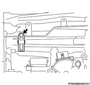
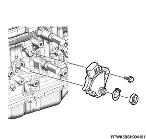
46. Output speed sensor installation
1) Install the output speed sensor to the transmission case.
Caution
- Be careful not to damage the output speed sensor.
Tightening torque: 5 N・m { 0.5 kgf・m / 44 lb・in }
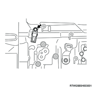
47. Turbine speed sensor installation
1) Install the turbine speed sensor to the transmission case.
Caution
- Be careful not to damage the turbine speed sensor.
Tightening torque: 5 N・m { 0.5 kgf・m / 44 lb・in }
48. Inhibitor switch installation
1) Install the inhibitor switch onto the manual valve lever shaft and temporarily install the bolt.
Note
- Tighten the bolt after adjusting the inhibitor switch to the N position.
2) Install the new lock washer with the new nut to the inhibitor switch.
Caution
- Do not reuse the lock washers and nuts.
Tightening torque: 7 N・m { 0.7 kgf・m / 62 lb・in }
3) Using a screwdriver, stake the lock washer.

4) Adjust the manual valve lever shaft to the N position.
5) Align the groove and neutral basic line.
6) Hold in position and tighten the bolt.
Tightening torque: 13 N・m { 1.3 kgf・m / 115 lb・in }
Legend
- Neutral basic line
- Groove
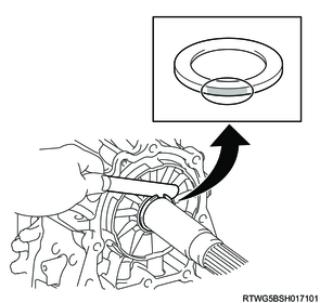
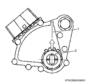
49. Torque converter assembly installation
1) Using a screwdriver, position the drive gear on the oil pump assembly in the center. Then install the torque converter assembly on the transmission case.
Caution
- Be careful not to damage the oil pump oil seal.
- Be careful not to drop the torque converter assembly.
Warning
- Be careful not to pinch fingers.
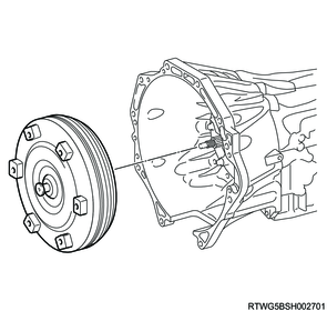
2) Measure the dimension from the end face of the converter housing to the torque converter assembly as shown in the figure, and check that the torque converter assembly is installed properly.
Over than
42.5 mm { 1.6732 in }

50. Transfer installation
1. 4WD models
Refer to "3.Driveline, Axle 3D.Transfer Case transfer installation".