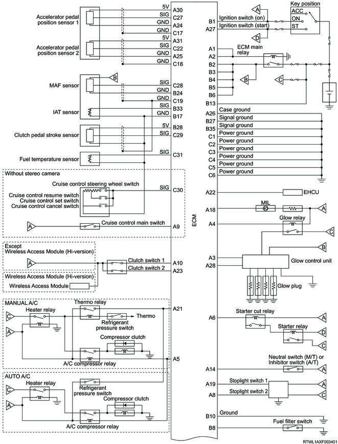
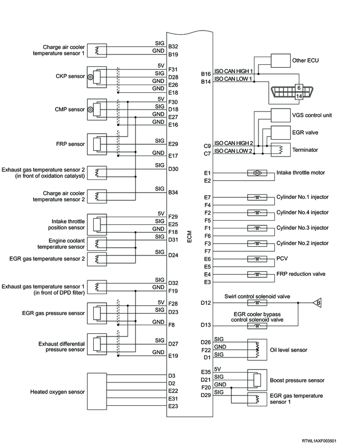
1. General circuit diagram
1/2
2/2
Note
- The components connected to the ECM may vary depending on the vehicle specifications.
2. ECM outline
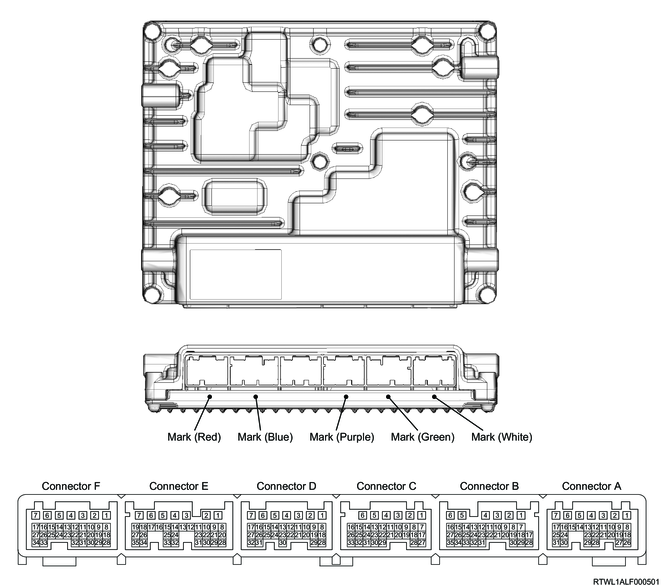
3. ECM pin layout
| PIN No. |
Pin function |
| 1 |
ECM main relay control |
| 2 |
ECM main relay control |
| 3 |
Glow plug control signal from ECM |
| 4 |
Glow relay control |
| 5 |
A/C compressor relay control |
| 6 |
Starter cut relay control |
| 7 |
- |
| 8 |
Stoplight switch 2 signal |
| 9 |
Cruise control main switch signal |
| 10 |
Clutch switch 1 signal |
| 11 |
- |
| 12 |
- |
| 13 |
- |
| 14 |
Neutral switch signal (M/T) |
| Inhibitor switch signal (A/T) |
|
| 15 |
- |
| 16 |
- |
| 17 |
- |
| 18 |
MIL control |
| 19 |
Stoplight switch 1 signal |
| 20 |
- |
| 21 |
Thermo relay signal (manual A/C) |
| Refrigerant pressure switch signal (auto A/C) |
|
| 22 |
Vehicle speed signal |
| 23 |
Clutch switch 2 signal |
| 24 |
Accelerator pedal position sensor 1 low reference |
| 25 |
Accelerator pedal position sensor 2 low reference |
| 26 |
ECM case ground |
| 27 |
Ignition voltage (start) |
| 28 |
Glow plug diagnosis signal to ECM |
| 29 |
- |
| 30 |
Accelerator pedal position sensor 1, 5 volts reference |
| 31 |
Accelerator pedal position sensor 2, 5 volts reference |
| PIN No. |
Pin function |
| 1 |
Ignition voltage (ON) |
| 2 |
Battery voltage |
| 3 |
Battery voltage |
| 4 |
Battery voltage |
| 5 |
Battery voltage |
| 6 |
Battery voltage |
| 7 |
- |
| 8 |
Fuel filter switch signal |
| 9 |
- |
| 10 |
Ground |
| 11 |
- |
| 12 |
- |
| 13 |
Battery voltage |
| 14 |
ISO CAN low 1 signal |
| 15 |
- |
| 16 |
ISO CAN high 1 signal |
| 17 |
IAT sensor, Cruise control switch, Clutch pedal stroke sensor and Fuel temperature sensor low reference |
| 18 |
- |
| 19 |
Charge air cooler temperature sensor 1 low reference |
| 20 |
- |
| 21 |
- |
| 22 |
- |
| 23 |
- |
| 24 |
MAF sensor low reference |
| 25 |
- |
| 26 |
- |
| 27 |
ECM signal ground |
| 28 |
Clutch pedal stroke sensor 5 volts reference |
| 29 |
- |
| 30 |
- |
| 31 |
- |
| 32 |
Charge air cooler temperature sensor 1 signal |
| 33 |
IAT sensor signal |
| 34 |
Charge air cooler temperature sensor 2 signal |
| 35 |
ECM signal ground |
| PIN No. |
Pin function |
| 1 |
ECM power ground |
| 2 |
ECM power ground |
| 3 |
ECM power ground |
| 4 |
ECM power ground |
| 5 |
ECM power ground |
| 6 |
ECM power ground |
| 7 |
ISO CAN low 2 signal |
| 8 |
- |
| 9 |
ISO CAN high 2 signal |
| 10 |
- |
| 11 |
- |
| 12 |
- |
| 13 |
- |
| 14 |
- |
| 15 |
- |
| 16 |
- |
| 17 |
Accelerator pedal position sensor 1 shield ground |
| 18 |
Accelerator pedal position sensor 2 shield ground |
| 19 |
MAF sensor and Clutch pedal stroke sensor shield ground |
| 20 |
- |
| 21 |
- |
| 22 |
Accelerator pedal position sensor 2 signal |
| 23 |
- |
| 24 |
- |
| 25 |
- |
| 26 |
- |
| 27 |
Accelerator pedal position sensor 1 signal |
| 28 |
MAF sensor signal |
| 29 |
Clutch pedal stroke sensor signal |
| 30 |
Cruise control switch signal |
| 31 |
Fuel temperature sensor signal |
| 32 |
- |
| 33 |
- |
| PIN No. |
Pin function |
| 1 |
Oil level sensor (oil level) signal |
| 2 |
Heated oxygen sensor heater low side |
| 3 |
Heated oxygen sensor heater high side |
| 4 |
- |
| 5 |
- |
| 6 |
- |
| 7 |
- |
| 8 |
- |
| 9 |
- |
| 10 |
- |
| 11 |
- |
| 12 |
Swirl control solenoid valve control |
| 13 |
EGR cooler bypass control solenoid valve control |
| 14 |
- |
| 15 |
- |
| 16 |
- |
| 17 |
- |
| 18 |
CMP sensor signal |
| 19 |
- |
| 20 |
- |
| 21 |
Boost pressure sensor signal |
| 22 |
- |
| 23 |
EGR gas pressure sensor signal |
| 24 |
EGR gas temperature sensor 2 signal |
| 25 |
- |
| 26 |
Oil level sensor (oil temperature) signal |
| 27 |
Exhaust differential pressure sensor signal |
| 28 |
CKP sensor signal |
| 29 |
EGR gas temperature sensor 1 signal |
| 30 |
Exhaust gas temperature sensor 2 signal |
| 31 |
Engine coolant temperature sensor signal |
| 32 |
Exhaust gas temperature sensor 1 signal |
| PIN No. |
Pin function |
| 1 |
Intake throttle motor 1 |
| 2 |
Intake throttle motor 2 |
| 3 |
FRP reduction valve low side |
| 4 |
FRP reduction valve high side |
| 5 |
PCV low side |
| 6 |
PCV high side |
| 7 |
Cylinder No. 1 injector solenoid control |
| 8 |
- |
| 9 |
- |
| 10 |
- |
| 11 |
- |
| 12 |
- |
| 13 |
- |
| 14 |
- |
| 15 |
- |
| 16 |
CMP sensor shield ground |
| 17 |
FRP sensor shield ground |
| 18 |
CKP sensor shield ground |
| 19 |
- |
| 20 |
- |
| 21 |
- |
| 22 |
Heated oxygen sensor pump current (IP) |
| 23 |
Heated oxygen sensor low reference (VM) |
| 24 |
- |
| 25 |
Intake throttle position sensor signal |
| 26 |
CKP sensor low reference |
| 27 |
CMP sensor, FRP sensor, Exhaust gas temperature sensor 2, and Charge air cooler temperature sensor 2 low reference |
| 28 |
- |
| 29 |
FRP sensor signal |
| 30 |
- |
| 31 |
Heated oxygen sensor reference voltage (UN) |
| 32 |
- |
| 33 |
- |
| 34 |
- |
| 35 |
Boost pressure sensor 5 volts reference |
| PIN No. |
Pin function |
| 1 |
Cylinder No. 3 injector solenoid control |
| 2 |
Cylinder No. 4 injector solenoid control |
| 3 |
Cylinder No. 2 injector solenoid control |
| 4 |
Cylinder No. 1 injector charge voltage |
| 5 |
Cylinder No. 4 injector charge voltage |
| 6 |
Cylinder No. 3 injector charge voltage |
| 7 |
Cylinder No. 2 injector charge voltage |
| 8 |
EGR gas pressure sensor shield ground |
| 9 |
- |
| 10 |
- |
| 11 |
- |
| 12 |
- |
| 13 |
- |
| 14 |
- |
| 15 |
- |
| 16 |
- |
| 17 |
- |
| 18 |
Intake throttle position sensor, engine coolant temperature sensor, and EGR gas temperature sensor 2 low reference |
| 19 |
Exhaust gas temperature sensor 1, EGR gas pressure sensor, and Exhaust differential pressure sensor low reference |
| 20 |
Boost pressure sensor and EGR gas temperature sensor 1 low reference |
| 21 |
- |
| 22 |
Oil level sensor low reference |
| 23 |
- |
| 24 |
- |
| 25 |
- |
| 26 |
- |
| 27 |
- |
| 28 |
EGR gas pressure sensor and Exhaust differential pressure sensor 5 volts reference |
| 29 |
Intake throttle position sensor 5 volts reference |
| 30 |
CMP sensor and FRP sensor 5 volts reference |
| 31 |
CKP sensor 5 volts reference |
| 32 |
- |
| 33 |
- |
| 34 |
- |