Lost communication with the information module (models without radar sensor and stereo camera) (Information Module)
1. Information module schematic circuit diagram
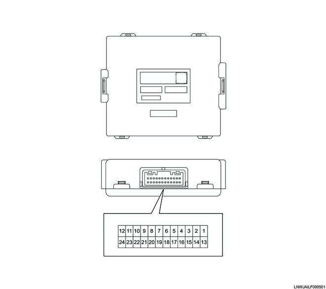
2. Information module outline view and connector pin layout
Connector (24 pin)
PIN No.
|
Pin function
|
1
|
Ignition power supply
|
2
|
-
|
3
|
Ground
|
4
|
-
|
5
|
-
|
6
|
-
|
7
|
-
|
8
|
-
|
9
|
-
|
10
|
-
|
11
|
Chassis CAN (High)
|
12
|
Powertrain CAN (High)
|
13
|
Battery power supply
|
14
|
-
|
15
|
-
|
16
|
-
|
17
|
-
|
18
|
-
|
19
|
-
|
20
|
-
|
21
|
-
|
22
|
-
|
23
|
Chassis CAN (Low)
|
24
|
Powertrain CAN (Low)
|
Copyright Mazda Motor Corporation. All rights reserved.