Diagnostic system check - central gateway controls (Central GateWay)
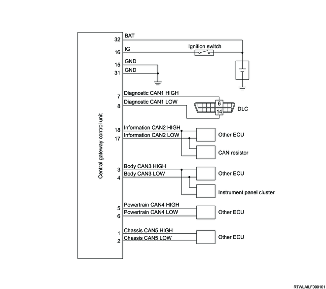
1. Central gateway control unit general circuit diagram
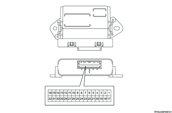
2. Central gateway control unit outline view and connector face
Pin No.
|
Pin function
|
1
|
Chassis CAN5 (High)
|
2
|
Chassis CAN5 (Low)
|
3
|
Body CAN3 (High)
|
4
|
Body CAN3 (Low)
|
5
|
Powertrain CAN4 (High)
|
6
|
Powertrain CAN4 (Low)
|
7
|
Diagnostic CAN1 (High)
|
8
|
Diagnostic CAN1 (Low)
|
9
|
-
|
10
|
-
|
11
|
-
|
12
|
-
|
13
|
-
|
14
|
-
|
15
|
Ground
|
16
|
Ignition power supply
|
17
|
Information CAN2 (Low)
|
18
|
Information CAN2 (High)
|
19
|
-
|
20
|
-
|
21
|
-
|
22
|
-
|
23
|
-
|
24
|
-
|
25
|
-
|
26
|
-
|
27
|
-
|
28
|
-
|
29
|
-
|
30
|
-
|
31
|
Ground
|
32
|
Battery power supply
|
Copyright Mazda Motor Corporation. All rights reserved.