DTC U1001[00] Lost Communication With Stereo Camera Module (Information Module)
1. Information module schematic circuit diagram
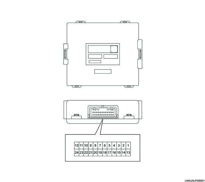
2. Information module outline view and connector pin layout
Connector (24 pin)
PIN No.
|
Pin function
|
1
|
Ignition power supply
|
2
|
-
|
3
|
Ground
|
4
|
-
|
5
|
-
|
6
|
-
|
7
|
-
|
8
|
-
|
9
|
-
|
10
|
-
|
11
|
Chassis CAN (High)
|
12
|
Powertrain CAN (High)
|
13
|
Battery power supply
|
14
|
-
|
15
|
-
|
16
|
-
|
17
|
-
|
18
|
-
|
19
|
-
|
20
|
-
|
21
|
-
|
22
|
-
|
23
|
Chassis CAN (Low)
|
24
|
Powertrain CAN (Low)
|
Copyright Mazda Motor Corporation. All rights reserved.