1. Rear differential lock control unit general circuit diagram.

2. Rear differential lock control unit outline view and connector pin layout
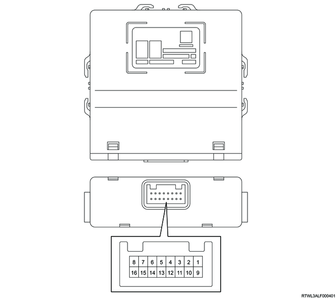
| Pin No. |
Pin function |
| 1 |
CAN (High) |
| 2 |
Ignition power supply |
| 3 |
- |
| 4 |
Rear differential lock switch signal |
| 5 |
- |
| 6 |
- |
| 7 |
Differential lock coil ground |
| 8 |
Differential lock coil control |
| 9 |
CAN (Low) |
| 10 |
Battery power supply |
| 11 |
- |
| 12 |
- |
| 13 |
Differential lock position switch signal |
| 14 |
- |
| 15 |
Ground |
| 16 |
Differential lock coil power supply |