BSM OFF indicator light illuminating circuit system check (Radar Sensor (Left))
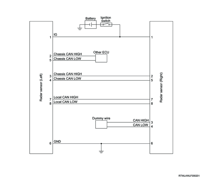
1. Radar sensor schematic
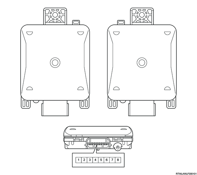
2. Radar sensor outline view and connector pin layout
Radar sensor (Right) connector
PIN No.
|
Pin function
|
1
|
Ignition power supply
|
2
|
Chassis CAN (High)
|
3
|
-
|
4
|
-
|
5
|
Chassis CAN (Low)
|
6
|
Ground
|
7
|
Local CAN (High)
|
8
|
Local CAN (Low)
|
Radar sensor (Left) connector
PIN No.
|
Pin function
|
1
|
Ignition power supply
|
2
|
Chassis CAN (High)
|
3
|
Chassis CAN (High)
|
4
|
Chassis CAN (Low)
|
5
|
Chassis CAN (Low)
|
6
|
Ground
|
7
|
Local CAN (High)
|
8
|
Local CAN (Low)
|
Copyright Mazda Motor Corporation. All rights reserved.