1. TCCM schematic circuit diagram

2. TCCM outline view and connector pin layout
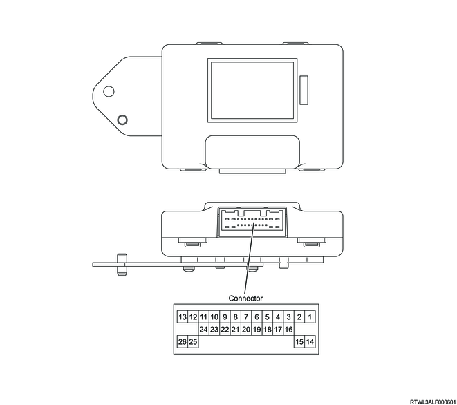
| Terminal No. |
Signal name |
| 1 |
Ignition voltage |
| 2 |
Battery voltage |
| 3 |
- |
| 4 |
CAN2 High |
| 5 |
- |
| 6 |
CAN1 Low |
| 7 |
- |
| 8 |
2-4 switch |
| 9 |
- |
| 10 |
Axle switch |
| 11 |
- |
| 12 |
Shift-on-the-fly actuator drive signal A |
| 13 |
- |
| 14 |
Ground |
| 15 |
Ground |
| 16 |
CAN2 Low |
| 17 |
- |
| 18 |
CAN1 High |
| 19 |
- |
| 20 |
4WD switch signal 4H |
| 21 |
- |
| 22 |
Transfer neutral switch |
| 23 |
- |
| 24 |
4WD switch signal 2H |
| 25 |
- |
| 26 |
Shift-on-the-fly actuator drive signal B |