|
1
|
VERIFY FREEZE FRAME DATA (MODE 2)/SNAPSHOT DATA HAS BEEN RECORDED
• Has the FREEZE FRAME DATA (Mode 2)/snapshot data been recorded?
|
Yes
|
Go to the next step.
|
|
No
|
Record the FREEZE FRAME DATA (Mode 2)/snapshot data on the repair order, then go to the next step.
|
|
2
|
VERIFY RELATED SERVICE INFORMATION AVAILABILITY
• Verify related Service Information availability.
• Is any related Service Information available?
|
Yes
|
Perform repair or diagnosis according to the available Service Information.
• If the vehicle is not repaired, go to the next step.
|
|
No
|
Go to the next step.
|
|
3
|
VERIFY RELATED PENDING CODE AND/OR DTC
• Switch the ignition off, then ON (engine off).
• Perform the Pending Trouble Code Access Procedure and DTC Reading Procedure.
• Are any other PENDING CODEs and/or DTCs present?
|
Yes
|
Go to the applicable PENDING CODE or DTC inspection.
|
|
No
|
Go to the next step.
|
|
4
|
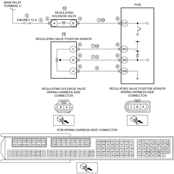
INSPECT REGULATING SOLENOID VALVE CONNECTOR CONDITION
• Switch the ignition off.
• Disconnect the regulating solenoid valve connector.
• Inspect for poor connection (such as damaged/pulled-out pins, corrosion).
• Is there any malfunction?
|
Yes
|
Repair or replace the connector and/or terminals, then go to Step 14.
|
|
No
|
Go to the next step.
|
|
5
|
INSPECT REGULATING SOLENOID VALVE POWER SUPPLY CIRCUIT FOR SHORT TO GROUND OR OPEN CIRCUIT
• Verify that the regulating solenoid valve connector is disconnected.
• Switch the ignition ON (engine off).
• Measure the voltage at the regulating solenoid valve terminal A (wiring harness-side).
• Is the voltage B+?
|
Yes
|
Go to the next step.
|
|
No
|
Inspect the ENGINE2 15 A fuse.
• If the fuse is blown:
-
― Repair or replace the wiring harness for a possible short to ground.
― Replace the fuse.
• If the fuse is deteriorated:
-
― Replace the fuse.
• If the fuse is normal:
-
― Repair or replace the wiring harness for a possible open circuit.
Go to Step 14.
|
|
6
|
INSPECT REGULATING VALVE POSITION SENSOR CONNECTOR CONDITION
• Switch the ignition off.
• Disconnect the regulating valve position sensor connector.
• Inspect for poor connection (such as damaged/pulled-out pins, corrosion).
• Is there any malfunction?
|
Yes
|
Repair or replace the connector and/or terminals, then go to Step 14.
|
|
No
|
Go to the next step.
|
|
7
|
INSPECT REGULATING SOLENOID VALVE CIRCUIT AND REGULATING VALVE POSITION SENSOR CIRCUIT FOR SHORT TO GROUND
• Verify that the regulating solenoid valve and regulating valve position sensor connectors are disconnected.
• Inspect for continuity between the following terminals (wiring harness-side) and body ground:
-
― Regulating solenoid valve terminal B
― Regulating valve position sensor terminal C
― Regulating valve position sensor terminal B
• Is there continuity?
|
Yes
|
If the short to ground circuit could be detected in the wiring harness:
• Repair or replace the wiring harness for a possible short to ground.
If the short to ground circuit could not be detected in the wiring harness:
• Replace the PCM (short to ground in the PCM internal circuit).
Go to Step 14.
|
|
No
|
Go to the next step.
|
|
8
|
INSPECT PCM CONNECTOR CONDITION
• Disconnect the PCM connector.
• Inspect for poor connection (such as damaged/pulled-out pins, corrosion).
• Is there any malfunction?
|
Yes
|
Repair or replace the connector and/or terminals, then go to Step 14.
|
|
No
|
Go to the next step.
|
|
9
|
INSPECT REGULATING VALVE POSITION SENSOR SIGNAL CIRCUIT AND GROUND CIRCUIT FOR SHORT TO EACH OTHER
• Verify that the regulating solenoid valve and regulating valve position sensor and PCM connectors are disconnected.
• Inspect for continuity between regulating valve position sensor terminals B and A (wiring harness-side).
• Is there continuity?
|
Yes
|
Repair or replace the wiring harness for a possible short to each other, then go to Step 14.
|
|
No
|
Go to the next step.
|
|
10
|
INSPECT REGULATING SOLENOID VALVE CIRCUIT AND REGULATING VALVE POSITION SENSOR CIRCUIT FOR OPEN CIRCUIT
• Verify that the regulating solenoid valve and regulating valve position sensor and PCM connectors are disconnected.
• Inspect for continuity between the following terminals (wiring harness-side):
-
― Regulating solenoid valve terminal B—PCM terminal 1CP
― Regulating valve position sensor terminal C—PCM terminal 1BO
• Is there continuity?
|
Yes
|
Go to the next step.
|
|
No
|
Repair or the replace the wiring harness for a possible open circuit, then go to Step 14.
|
|
11
|
INSPECT VACUUM PIPING AND POSITIVE PRESSURE PIPING OF REGULATING VALVE
• Inspect vacuum piping and positive pressure piping of regulating valve.
• Is there hose leakage or damage in the vacuum piping and positive pressure piping?
|
Yes
|
Repair or replace the malfunctioning part according to the inspection results, then go to Step 14.
|
|
No
|
Go to the next step.
|
|
12
|
INSPECT REGULATING SOLENOID VALVE
• Inspect the regulating solenoid valve.
• Is there any malfunction?
|
Yes
|
Replace the regulating solenoid valve, then go to Step 14.
|
|
No
|
Go to the next step.
|
|
13
|
INSPECT REGULATING VALVE POSITION SENSOR
• Reconnect all disconnected connectors.
• Inspect the regulating valve position sensor.
• Is there any malfunction?
|
Yes
|
Replace the regulating valve actuator, then go to the next step.
|
|
No
|
Go to the next step.
|
|
14
|
VERIFY DTC TROUBLESHOOTING COMPLETED
• Always reconnect all disconnected connectors.
• Clear the DTC from the PCM memory using the M-MDS.
• Start the engine and warm it up completely.
-
Caution
-
• While performing this step, always operate the vehicle in a safe and lawful manner.
• When the M-MDS is used to observe monitor system status while driving, be sure to have another technician with you, or record the data in the M-MDS using the PID/DATA MONITOR AND RECORD capturing function and inspect later.
• Drive the vehicle under the FREEZE FRAME DATA (Mode 2)/snapshot data condition.
• Perform the Pending Trouble Code Access Procedure.
• Is the PENDING CODE for this DTC present?
|
Yes
|
Repeat the inspection from Step 1.
• If the malfunction recurs, replace the PCM.
Go to the next step.
|
|
No
|
Go to the next step.
|
|
15
|
VERIFY AFTER REPAIR PROCEDURE
• Perform the “AFTER REPAIR PROCEDURE”.
• Are any DTCs present?
|
Yes
|
Go to the applicable DTC inspection.
|
|
No
|
DTC troubleshooting completed.
|