DTC P245B:00 [SKYACTIV-D 2.2]


id0102s4886600

DTC P245B:00

EGR cooler bypass valve control: duty signal malfunction

DETECTION CONDITION
•  If the duty value is 95 % for 2 s, the PCM determines that there is a EGR cooler bypass valve actuator control system range/performance problem.
Diagnostic support note
•  This is a continuous monitor (CCM).
•  The check engine light illuminates if the PCM detects the above malfunction condition in two consecutive drive cycles or in one drive cycle while the DTC for the same malfunction has been stored in the PCM.
•  PENDING CODE is available if the PCM detects the above malfunction condition during the first drive cycle.
•  FREEZE FRAME DATA (Mode 2)/Snapshot data is available.
•  DTC is stored in the PCM memory.
FAIL-SAFE FUNCTION
•  Inhibits the two-stage turbo control.
•  Inhibits the EGR control.
•  Inhibits engine-stop by operating the i-stop function.
•  PCM restricts engine-transaxle integration control.
POSSIBLE CAUSE
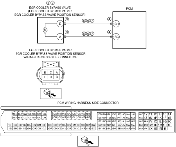
•  EGR cooler bypass valve/EGR cooler bypass valve position sensor connector or terminals malfunction
•  PCM connector or terminals malfunction
•  Open circuit in wiring harness between the following terminals:
―  EGR cooler bypass valve/EGR cooler bypass valve position sensor terminal E—PCM terminal 1BH
―  EGR cooler bypass valve/EGR cooler bypass valve position sensor terminal A—PCM terminal 1BC
•  Short to ground in wiring harness between the following terminals:
―  EGR cooler bypass valve/EGR cooler bypass valve position sensor terminal E—PCM terminal 1BH
―  EGR cooler bypass valve/EGR cooler bypass valve position sensor terminal A—PCM terminal 1BC
•  Short to power supply in wiring harness between the following terminals:
―  EGR cooler bypass valve/EGR cooler bypass valve position sensor terminal E—PCM terminal 1BH
―  EGR cooler bypass valve/EGR cooler bypass valve position sensor terminal A—PCM terminal 1BC
•  EGR cooler bypass valve position sensor malfunction
•  EGR cooler bypass valve malfunction
•  PCM malfunction

Diagnostic Procedure

STEP

INSPECTION

ACTION

1
VERIFY FREEZE FRAME DATA (MODE 2)/SNAPSHOT DATA HAS BEEN RECORDED
•  Has the FREEZE FRAME DATA (Mode 2)/snapshot data been recorded?
Yes
Go to the next step.
No
Record the FREEZE FRAME DATA (Mode 2)/snapshot data on the repair order, then go to the next step.
2
VERIFY RELATED SERVICE INFORMATION AVAILABILITY
•  Verify related Service Information availability.
•  Is any related Service Information available?
Yes
Perform repair or diagnosis according to the available Service Information.
•  If the vehicle is not repaired, go to the next step.
No
Go to the next step.
3
INSPECT EGR COOLER BYPASS VALVE/EGR COOLER BYPASS VALVE POSITION SENSOR CONNECTOR CONDITION
•  Switch the ignition off.
•  Disconnect the EGR cooler bypass valve/EGR cooler bypass valve position sensor connector.
•  Inspect for poor connection (such as damaged/pulled-out pins, corrosion).
•  Is there any malfunction?
Yes
Repair or replace the connector and/or terminals, then go to Step 10.
No
Go to the next step.
4
INSPECT PCM CONNECTOR CONDITION
•  Disconnect the PCM connector.
•  Inspect for poor connection (such as damaged/pulled-out pins, corrosion).
•  Is there any malfunction?
Yes
Repair or replace the connector and/or terminals, then go to Step 10.
No
Go to the next step.
5
INSPECT EGR COOLER BYPASS VALVE CIRCUIT FOR OPEN CIRCUIT
•  Verify that the EGR cooler bypass valve/EGR cooler bypass valve position sensor and PCM connectors are disconnected.
•  Inspect for continuity between the following terminals (wiring harness-side):
―  EGR cooler bypass valve/EGR cooler bypass valve position sensor terminal E—PCM terminal 1BH
―  EGR cooler bypass valve/EGR cooler bypass valve position sensor terminal A—PCM terminal 1BC
•  Is there continuity?
Yes
Go to the next step.
No
Repair or replace the wiring harness for a possible open circuit, then go to Step 10.
6
INSPECT EGR COOLER BYPASS VALVE POSITION SENSOR CIRCUIT FOR SHORT TO GROUND
•  Verify that the EGR cooler bypass valve/EGR cooler bypass valve position sensor and PCM connectors are disconnected.
•  Inspect for continuity between the following terminals (wiring harness-side) and body ground:
―  EGR cooler bypass valve/EGR cooler bypass valve position sensor terminal E
―  EGR cooler bypass valve/EGR cooler bypass valve position sensor terminal A
•  Is there continuity?
Yes
Repair or replace the wiring harness for a possible short to ground, then go to Step 10.
No
Go to the next step.
7
INSPECT EGR COOLER BYPASS VALVE CIRCUIT FOR SHORT TO POWER SUPPLY
•  Verify that the EGR cooler bypass valve/EGR cooler bypass valve position sensor and PCM connectors are disconnected.
•  Switch the ignition ON (engine off).
•  Measure the voltage at the following terminals (wiring harness-side):
―  EGR cooler bypass valve/EGR cooler bypass valve position sensor terminal E
―  EGR cooler bypass valve/EGR cooler bypass valve position sensor terminal A
•  Is the voltage 0 V?
Yes
Go to the next step.
No
Repair or replace the wiring harness for a possible short to power supply, then go to Step 10.
8
INSPECT EGR COOLER BYPASS VALVE POSITION SENSOR
•  Reconnect all disconnected connectors.
•  Inspect the EGR cooler bypass valve position sensor.
•  Is there any malfunction?
Yes
Replace the EGR cooler bypass valve, then go to Step 10.
No
Go to the next step.
9
INSPECT EGR COOLER BYPASS VALVE
•  Inspect the EGR cooler bypass valve.
•  Is there any malfunction?
Yes
Replace the EGR cooler bypass valve, then go to the next step.
No
Go to the next step.
10
VERIFY DTC TROUBLESHOOTING COMPLETED
•  Always reconnect all disconnected connectors.
•  Clear the DTC from the PCM memory using the M-MDS.
•  Perform the Pending Trouble Code Access Procedure.
•  Is the PENDING CODE for this DTC present?
Yes
Repeat the inspection from Step 1.
•  If the malfunction recurs, replace the PCM.
Go to the next step.
No
Go to the next step.
11
VERIFY AFTER REPAIR PROCEDURE
•  Perform the “AFTER REPAIR PROCEDURE”.
•  Are any DTCs present?
Yes
Go to the applicable DTC inspection.
No
DTC troubleshooting completed.