ac5wzn00002359
|
ON-BOARD DIAGNOSTIC SYSTEM FUNCTION
id030200108300
Malfunction Detection Function
Memory Function
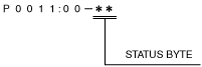
DTC 7-digit Code Definition
ac5wzn00002359
|
DTC Table
|
DTC |
Malfunction location |
4WD warning light condition |
Fail-safe |
Drive cycle |
Self test type*1 |
Memory function |
|---|---|---|---|---|---|---|
|
P164D:00
|
4WD CM configuration
|
Illuminated
|
X
|
—
|
C
|
X
|
|
P182F:00
|
4WD CM
|
Flashed
|
X
|
—
|
C
|
X
|
|
P1886:00
|
4WD CM
|
Illuminated
|
X
|
—
|
C
|
X
|
|
P1887:11
|
4WD solenoid circuit
|
Illuminated
|
X
|
—
|
C
|
X
|
|
P1887:12
|
4WD solenoid circuit
|
Illuminated
|
X
|
—
|
C
|
X
|
|
P1887:13
|
4WD solenoid circuit
|
Illuminated
|
X
|
—
|
C
|
X
|
|
P1887:14
|
4WD solenoid circuit
|
Illuminated
|
X
|
—
|
C
|
X
|
|
P187B:00
|
4WD solenoid circuit
|
Illuminated
|
X
|
—
|
C
|
X
|
|
P1888:11
|
Differential oil temperature sensor circuit
|
Illuminated
|
X
|
—
|
C
|
X
|
|
P1888:15
|
Differential oil temperature sensor circuit
|
Illuminated
|
X
|
—
|
C
|
X
|
|
P188A:00
|
4WD CM
|
Flashed
|
X
|
—
|
C
|
X
|
|
U0001:88
|
CAN system communication error
|
—
|
X
|
—
|
C
|
X
|
|
U0100:00
|
Communication error to PCM
|
—
|
X
|
—
|
C
|
X
|
|
U0101:00
|
CAN system communication error
|
—
|
X
|
—
|
C
|
X
|
|
U0121:00
|
CAN system communication error
|
—
|
X
|
—
|
C
|
X
|
|
U0401:68
|
Signal error from PCM
|
—
|
X
|
—
|
C
|
X
|
|
U0402:68
|
Signal error from TCM
|
—
|
X
|
—
|
C
|
X
|
|
U0415:68
|
Signal error from DSC HU/CM
|
—
|
X
|
—
|
C
|
X
|
|
U2100:00
|
4WD CM configuration
|
Illuminated
|
X
|
—
|
C
|
X
|
Status Byte for DTC
ac5wzn00002360
|
Fail-safe Function
|
DTC |
Fail-safe control status |
|---|---|
|
P164D:00
|
4WD operates by the specified data
|
|
P182F:00
|
4WD protection condition (4WD control paused)
|
|
P1886:00
|
Control disabled
|
|
P1887:11
|
Control disabled
|
|
P1887:12
|
Control disabled
|
|
P1887:13
|
Control disabled
|
|
P1887:14
|
Control disabled
|
|
P187B:00
|
Control disabled
|
|
P1888:11
|
Control disabled
|
|
P1888:15
|
Control disabled
|
|
P188A:00
|
4WD protection condition (4WD control paused)
|
|
U0001:88
|
Control disabled
|
|
U0100:00
|
4WD operates by the specified data
|
|
U0101:00
|
Lost gear position signal: 4WD operates by the specified data
Except above: Control disabled
|
|
U0121:00
|
Control disabled
|
|
U0401:68
|
• Gear position signal error (MTX)
• Except for gear position signal error
|
|
U0402:68
|
4WD operates by the specified data
|
|
U0415:68
|
Control disabled
|
|
U2100:00
|
4WD operates by the specified data
|
Snapshot Data Table
|
Snapshot data item |
Unit |
Data contents |
Data read/use method |
Corresponding data monitor items |
|
|---|---|---|---|---|---|
|
AAT
|
°C
|
°F
|
Ambient temperature
|
—
|
—
|
|
IC_VPWR
|
V
|
Instrument cluster power supply voltage
|
• The 4WD CM constantly receives the power supply voltage value of the instrument cluster sent via CAN signal from the instrument cluster.
• If a DTC is detected, the 4WD CM records the power supply voltage of the instrument cluster when the DTC was detected, and it is displayed in the M-MDS.
|
VPWR*1
|
|
|
IG-ON_TIMER
|
hh:mm:ss*2
|
Elapsed time since ignition was switched ON (engine off or on)
|
• The 4WD CM constantly receives the elapsed time since the ignition was switched ON (engine off or on) sent via CAN signal from the instrument cluster.
• If a DTC is detected, the 4WD CM records the elapsed time since the ignition was switched ON (engine off or on) when the DTC was detected, and it is displayed in the M-MDS.
|
—
|
|
|
PWR_MODE_KEY
|
Key Out/Key Recently Out (Position 0)/Accessory (Position 1)/Post Ignition (Position 2)/Ignition On (Position 2)/Running (Position 2)/Running - Starting
|
• Key Out: Ignition switched off
• Key Recently Out (Position 0): Elapsed time within 3 s since ignition was switched off
• Accessory (Position 1): Ignition is switched to ACC
• Post Ignition (Position 2): Elapsed time within 3 s since ignition was switched ON (engine off or on)
• Ignition On (Position 2): Ignition switched ON (engine off)
• Running (Position 2): Ignition switched ON (engine on)
• Running - Starting: Cranking condition
|
• The 4WD CM constantly receives the ignition switch status sent via CAN signal from the instrument cluster.
• If a DTC is detected, the 4WD CM records the ignition switch status when the DTC was detected, and it is displayed in the M-MDS.
|
—
|
|
|
TOTAL_DIST
|
km
|
Miles
|
Accumulated total traveled distance from completion of vehicle until 4WD CM detects DTC (Odometer value in instrument cluster)
|
The total traveled distance from which the 4WD CM detects DTCs to the present can be calculated by performing the following procedure.
1. Verify the odometer value in the instrument cluster.
2. Verify the snapshot data item TOTAL_DIST.
3. Subtract 2 from 1.
|
—
|
|
TOTAL_TIME
|
hh:mm:ss*2
|
Accumulated total elapsed time since vehicle completion until 4WD CM detects a DTC
|
The elapsed time from which the 4WD CM detects DTCs to the present can be calculated by performing the following procedure.
1. Verify the instrument cluster PID item TOTAL_TIME.
2. Verify the snapshot data item TOTAL_TIME.
3. Subtract 2 from 1.
|
TOTAL_TIME*1
|
|
External Tester Communication Function