am6zzw00012135
|
SHIFT-LOCK SYSTEM INSPECTION
id051800297100
Shift-Lock System Inspection
1. Switch the ignition ON (engine off).
2. Shift the selector lever to the P position.
3. Verify that the selector lever cannot be shifted from P to R position when the brake pedal is released.
4. Verify that the selector lever can be shifted from P to R position when the brake pedal is depressed.
Shift-Lock Solenoid Inspection
1. Disconnect the negative battery cable. (See NEGATIVE BATTERY CABLE DISCONNECTION/CONNECTION [SKYACTIV-G 2.0, SKYACTIV-G 2.5].) (See NEGATIVE BATTERY CABLE DISCONNECTION/CONNECTION [SKYACTIV-G 2.0, SKYACTIV-G 2.5 (WITHOUT i-stop)].) (See NEGATIVE BATTERY CABLE DISCONNECTION/CONNECTION [SKYACTIV-D 2.2].)
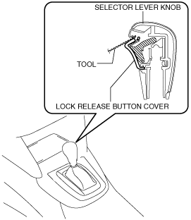
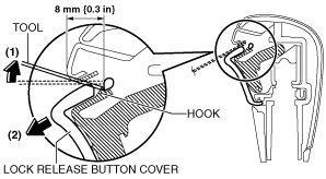
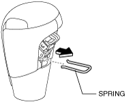
2. Perform the following procedure to remove the selector lever knob (type B).
am6zzw00012135
|
am6zzw00012136
|
am6zzw00012088
|
am6zzw00012089
|
3. Remove the front console. (See FRONT CONSOLE REMOVAL/INSTALLATION.)
4. Reconnect the negative battery cable. (See NEGATIVE BATTERY CABLE DISCONNECTION/CONNECTION [SKYACTIV-G 2.0, SKYACTIV-G 2.5].) (See NEGATIVE BATTERY CABLE DISCONNECTION/CONNECTION [SKYACTIV-G 2.0, SKYACTIV-G 2.5 (WITHOUT i-stop)].) (See NEGATIVE BATTERY CABLE DISCONNECTION/CONNECTION [SKYACTIV-D 2.2].)
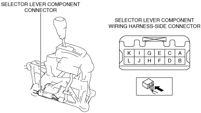
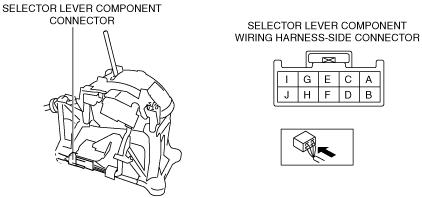
5. Verify that the voltages of each of the selector lever component terminals are as indicated in the table.
Type A
ac5wzw00006892
|
Type B
ac5wzw00006893
|
Shift-lock solenoid specification
|
Terminal |
Connected to |
Test condition |
Voltage (V) |
|---|---|---|---|
|
A
|
IG1 relay
|
Ignition switched ON (engine on)
|
B+
|
|
Except above
|
Below 1.0
|
||
|
H
|
Start stop unit
|
Under any condition
|
Below 1.0
|
Shift-lock Override Button Inspection
1. Switch the ignition to off.
2. Verify that the selector lever is in the P position.
3. Without the brake pedal depressed, verify that the selector lever cannot be shifted from the P position.
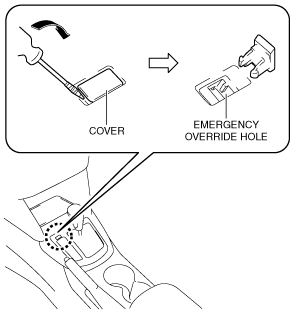
4. Remove the emergency override hole cover using a tape-wrapped flathead screwdriver.
ac5uuw00003353
|
5. Insert the flathead screwdriver into the emergency override hole and push it down.
6. Verify that the selector lever can be shifted from the P position.