|
1
|
INSPECT AIRFLOW MODE ACTUATOR CONNECTOR
• Switch the ignition off.
• Disconnect the negative battery cable.
• Inspect the connector and terminals (corrosion, damage, pin disconnection).
• Are the connector and terminals normal?
|
Yes
|
Go to the next step.
|
|
No
|
Repair/replace the connector or terminal.
After repair procedure, go to the next step.
|
|
2
|
INSPECT AIRFLOW MODE ACTUATOR
• Inspect the airflow mode actuator.
• Is it normal?
|
Yes
|
Go to the next step.
|
|
No
|
Replace the airflow mode actuator.
Go to the next step.
|
|
3
|
INSPECT AIRFLOW MODE ACTUATOR (POTENTIOMETER) CIRCUIT FOR OPEN CIRCUIT
• Disconnect the climate control unit connector and the airflow mode actuator connector.
• Inspect for continuity between the following terminals (wiring harness-side):
-
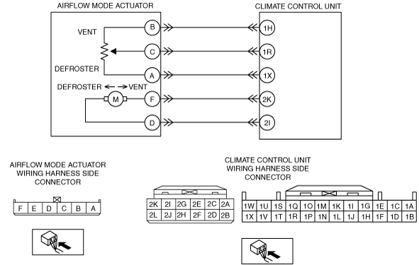
― Climate control unit terminal 1H—airflow mode actuator terminal B
― Climate control unit terminal 1R—airflow mode actuator terminal C
― Climate control unit terminal 1X—airflow mode actuator terminal A
• Is there continuity?
|
Yes
|
Go to the next step.
|
|
No
|
Repair the wiring harness.
Go to the next step.
|
|
4
|
INSPECT AIRFLOW MODE ACTUATOR (POTENTIOMETER) SHORT TO POWER SUPPLY
• Connect the negative battery cable.
• Switch the ignition ON (engine off or on).
• Measure the voltage at the following terminals (wiring harness-side):
-
― Climate control unit terminal 1R
• Is the voltage 0V?
|
Yes
|
The system is normal at present.
Go to the next step.
|
|
No
|
Repair/replace the malfunctioning vehicle wiring harness.
After repair procedure, go to the next step.
|
|
5
|
VERIFY CLIMATE CONTROL UNIT CONNECTOR CONDITION
• Switch the ignition off.
• Disconnect the negative battery cable.
• Inspect the connector and terminals (corrosion, damage, pin disconnection).
• Are the connector and terminals normal?
|
Yes
|
Go to the next step.
|
|
No
|
Repair/replace the malfunctioning vehicle wiring harness, connector, or terminal.
After repair procedure, go to the next step.
|
|
6
|
VERIFY THAT SAME DTC IS NOT OUTPUT AGAIN
• Reconnect the disconnected connectors.
• Connect the negative battery cable.
• Clear the past malfunction from memory.
• Verify DTCs.
• Is DTC B1C1C:12, B1C1C:13 output?
|
Yes
|
Repeat the inspection from Step 1.
• If the malfunction does not recur, go to the next step.
• If the malfunction recurs, replace the climate control unit.
Go to the next step.
|
|
No
|
Go to the next step.
|
|
7
|
VERIFY THAT NO OTHER DTCs ARE PRESENT
• Verify other DTCs displayed.
• Are any other DTCs output?
|
Yes
|
Perform the corresponding DTC inspection.
|
|
No
|
DTC troubleshooting completed.
|