|
ac5wzw00006468
BLOWER UNIT REMOVAL/INSTALLATION
id071100800500
L.H.D.
1. Disconnect the negative battery cable. (See NEGATIVE BATTERY CABLE DISCONNECTION/CONNECTION [SKYACTIV-G 2.0, SKYACTIV-G 2.5].)(See NEGATIVE BATTERY CABLE DISCONNECTION/CONNECTION [SKYACTIV-G 2.0, SKYACTIV-G 2.5 (WITHOUT i-stop)].)(See NEGATIVE BATTERY CABLE DISCONNECTION/CONNECTION [SKYACTIV-D 2.2].)
2. Remove the following parts:
3. Disconnect the blower motor connector.
ac5wzw00006468
|
4. Disconnect the air intake actuator connector.
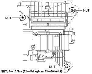
5. Remove the blower unit installation nuts.
ac5wzw00001791
|
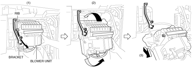
6. Pass the blower unit projection between the brackets shown in the figure (1) and rotate the blower unit (2).
ac5wzw00001792
|
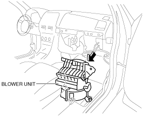
7. Pull out the blower unit in the direction of the arrow (3).
8. Remove the blower unit.
ac5wzw00001793
|
9. Install in the reverse order of removal.
R.H.D.
1. Disconnect the negative battery cable. (See NEGATIVE BATTERY CABLE DISCONNECTION/CONNECTION [SKYACTIV-G 2.0, SKYACTIV-G 2.5].)(See NEGATIVE BATTERY CABLE DISCONNECTION/CONNECTION [SKYACTIV-G 2.0, SKYACTIV-G 2.5 (WITHOUT i-stop)].)(See NEGATIVE BATTERY CABLE DISCONNECTION/CONNECTION [SKYACTIV-D 2.2].)
2. Remove the following parts:
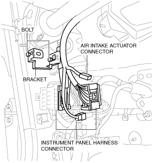
3. Disconnect the air intake actuator connector.
ac5wzw00001794
|
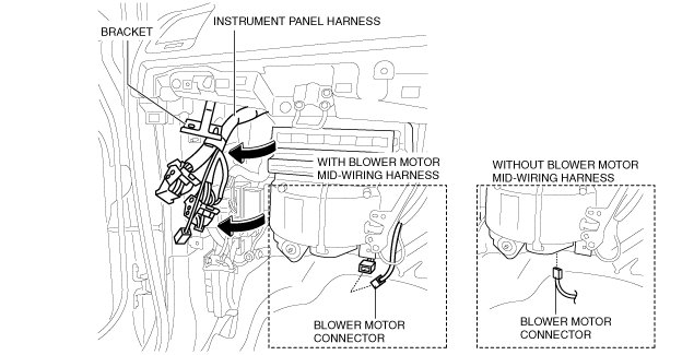
4. Disconnect the instrument panel harness connector.
5. Remove the bolt, then remove the instrument panel harness bracket.
6. Set the instrument panel harness connector and bracket out of the way as shown in the figure.
ac5wzw00006469
|
7. Disconnect the blower motor connector.
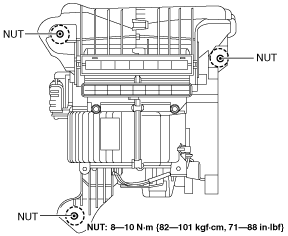
8. Remove the blower unit installation nuts.
ac5wzw00001796
|
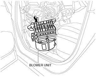
9. Remove the blower unit.
ac5wzw00001797
|
10. Install in the reverse order of removal.