 |
ac5uuw00001758
LOWER PANEL REMOVAL/INSTALLATION
id091700801100
Driver-side
1. Disconnect the negative battery cable. (See NEGATIVE BATTERY CABLE DISCONNECTION/CONNECTION [SKYACTIV-G 2.0, SKYACTIV-G 2.5].) (See NEGATIVE BATTERY CABLE DISCONNECTION/CONNECTION [SKYACTIV-G 2.0, SKYACTIV-G 2.5 (WITHOUT i-stop)].) (See NEGATIVE BATTERY CABLE DISCONNECTION/CONNECTION [SKYACTIV-D 2.2].)
2. Remove the following parts:
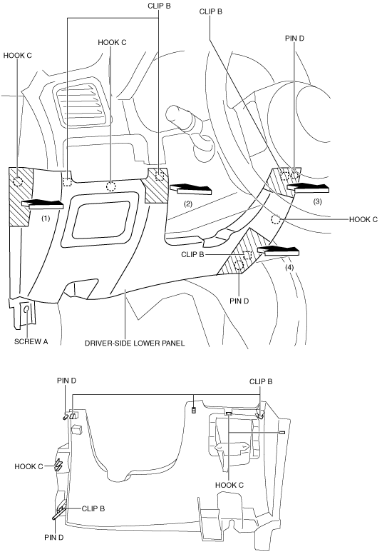
3. Remove the screw A.
ac5uuw00001758
|
4. Take the shaded area shown in the figure, and pull the driver-side lower panel in the direction of the arrow in the order of (1), (2), (3),(4) and remove it while detaching clips B, hooks C and pins D.
5. Install in the reverse order of removal.
Passenger-side
Removal
1. Disconnect the negative battery cable.
2. Remove the following parts:
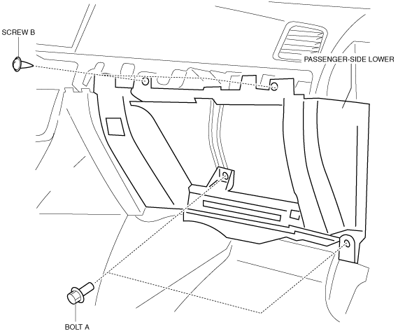
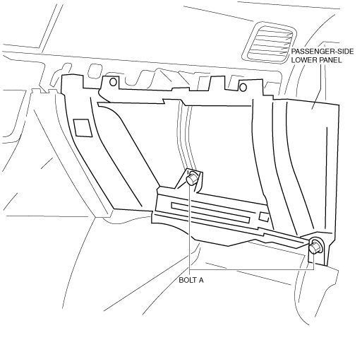
3. Remova bolts A.
4. Remova screws B.
ac5wzw00005559
|
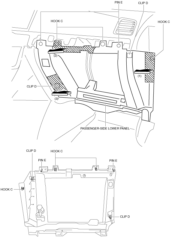
5. Take the shaded area shown in the figure, and pull the passenger-side lower panel in the direction of the arrow in the order of (1), (2), (3) and remove it while detaching hooks C, clips D and pins E.
ac5wzw00005553
|
Installation
1. Install hooks C, clips D, and pins E while pressing the shaded area shown in the figure for the passenger-side lower panel in the direction of the arrow in the order of (1), (2), and (3).
ac5wzw00005554
|
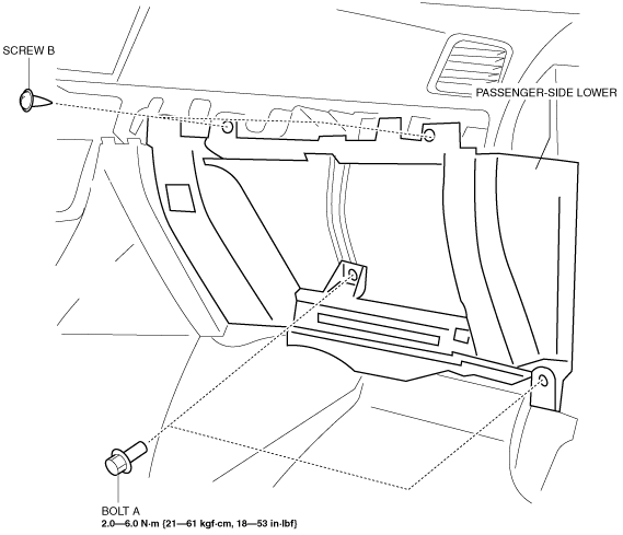
2. Install screws B.
3. Install bolts A, and then install the passenger-side lower panel.
ac5wzw00005552
|
4. Install the following parts:
5. Connect the negative battery cable. (See NEGATIVE BATTERY CABLE DISCONNECTION/CONNECTION [SKYACTIV-G 2.0, SKYACTIV-G 2.5].) (See NEGATIVE BATTERY CABLE DISCONNECTION/CONNECTION [SKYACTIV-G 2.0, SKYACTIV-G 2.5 (WITHOUT i-stop)].) (See NEGATIVE BATTERY CABLE DISCONNECTION/CONNECTION [SKYACTIV-D 2.2].)
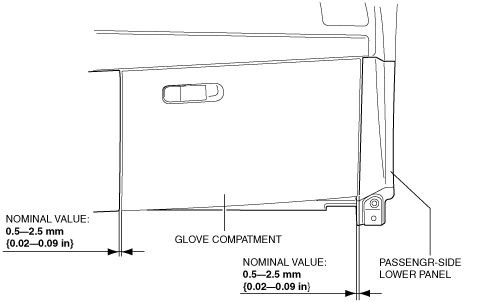
6. After installing the passenger-side lower panel and glove compartment, measure the clearance, and verify that the measurement value is within the specification shown in the figure.
ac5wzw00005555
|
Passenger-side lower panel adjustment
1. Remove the grove compartment. (See GLOVE COMPARTMENT REMOVAL/INSTALLATION)
2. Loosen bolts A.
ac5wzw00005556
|
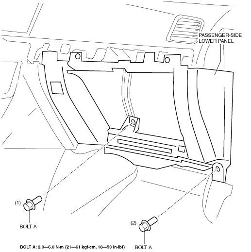
3. Remove bolts A.
4. Install bolts A in the order of (1), (2) shown in the figure.
ac5wzw00005557
|
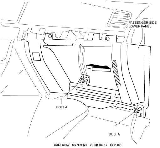
5. Install bolts A in the order of (1) and (2) while pressing the shaded area shown in the figure for the passenger-side lower panel.
ac5wzw00005558
|
6. Install the glove compartment, measure the clearance between the glove compartment and passenger-side lower panel again, and verify that it is within the specification.