|
1
|
PERFORM INSTRUMENT CLUSTER CONFIGURATION (USING AS-BUILT DATA)
• Using the M-MDS, perform the instrument cluster configuration with the As-Built data.
• Clear DTC for the start stop unit using the M-MDS.
• Switch the ignition ON (engine off or on) and wait for 5 s or more.
• Perform the DTC inspection for the start stop unit using the M-MDS.
• Is DTC B10AC:13 displayed?
|
Yes
|
Using the M-MDS, re-perform the instrument cluster configuration using the As-Built data, then go to the next step.
|
|
No
|
Go to Step 8.
|
|
2
|
INSPECT CLOCK SPRING CONNECTOR CONDITION
• Switch the ignition to off.
• Disconnect the negative battery cable.
• Disconnect the clock spring connector.
• Inspect the connector engagement and connection condition and inspect the terminals for damage, deformation, corrosion, or disconnection.
• Is the connector normal?
|
Yes
|
Go to the next step.
|
|
No
|
Repair or replace the connector, then go to Step 7.
|
|
3
|
INSPECT CLOCK SPRING
• Inspect the clock spring.
• Is the clock spring normal?
|
Yes
|
Go to the next step.
|
|
No
|
Replace the clock spring, then go to Step 7.
|
|
4
|
INSPECT START STOP UNIT CONNECTOR CONDITION
• Disconnect the start stop unit connector.
• Inspect the connector engagement and connection condition and inspect the terminals for damage, deformation, corrosion, or disconnection.
• Is the connector normal?
|
Yes
|
Go to the next step.
|
|
No
|
Repair or replace the connector, then go to Step 7.
|
|
5
|
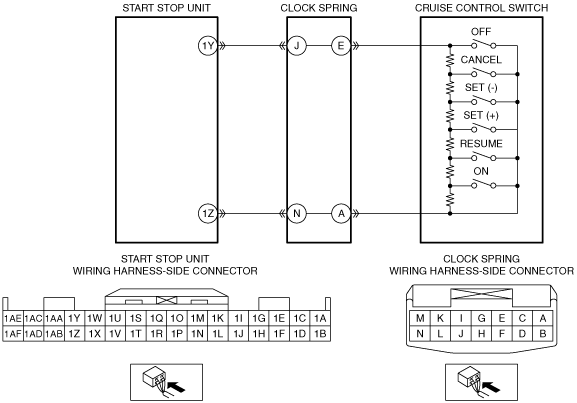
INSPECT CRUISE CONTROL SWITCH CIRCUIT FOR OPEN CIRCUIT
• Verify that the start stop unit and clock spring connectors are disconnected.
• Inspect the wiring harness between the following terminals (vehicle wiring harness side) for continuity.
-
― Start stop unit terminal 1Y and clock spring (start stop unit side) terminal J
― Start stop unit terminal 1Z and clock spring (start stop unit side) terminal N
• Is there continuity?
|
Yes
|
Go to the next step.
|
|
No
|
Repair or replace the wiring harness which has an open circuit, then go to Step 7.
|
|
6
|
INSPECT CRUISE CONTROL SWITCH
• Inspect the cruise control switch.
• Is the cruise control switch normal?
|
Yes
|
Go to the next step.
|
|
No
|
Replace the cruise control switch, then go to the next step.
|
|
7
|
VERIFY THAT REPAIRS HAVE BEEN COMPLETED
• Reconnect all the disconnected connectors.
• Reconnect the disconnected negative battery cable.
• Clear DTC for the start stop unit using the M-MDS.
• Switch the ignition ON (engine off or on) and wait for 5 s or more.
• Perform the DTC inspection for the start stop unit using the M-MDS.
• Is DTC B10AC:13 displayed?
|
Yes
|
Repeat the inspection from Step 1.
• If the malfunction recurs, replace the start stop unit, then go to the next step.
|
|
No
|
Go to the next step.
|
|
8
|
VERIFY IF OTHER DTCs DISPLAYED
• Are any other DTCs displayed?
|
Yes
|
Repair the malfunctioning part according to the applicable DTC troubleshooting.
|
|
No
|
DTC troubleshooting completed.
|