Step
Inspection
Action
1
VERIFY GPS ANTENNA RECEPTION CONDITION
• Stop the vehicle and leave it idling for 5 min in an area with clear visibility (no buildings or trees surrounding).
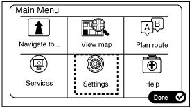
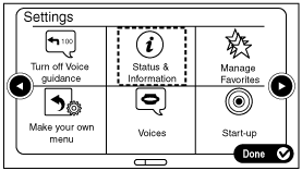
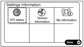
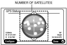
• Verify the GPS signal reception condition on the audio unit screen. (See Procedure for Displaying GPS status screen.)
• Is the GPS information displayed on the GPS status screen?
am6zzw00012225
|
-
Note
-
• If 4 or more satellites are displayed, the GPS signal reception strength is normal.
Yes
Replace the car-navigation unit.
No
Go to the next step.
2
VERIFY IF GPS ANTENNA RECEPTION IS OBSTRUCTED
• Is there an object on the dashboard which is interfering with GPS reception (such as devices installed by customer after installation)?
Yes
After explaining to the customer that device installed by the customer on the dashboard after the installation is interfering with GPS reception, remove the device.
After servicing, go to the next step.
No
Go to the next step.
3
VERIFY THE GPS ANTENNA RECEPTION SIGNAL
• Launch the audio unit diagnostic assist function.
• Select diagnostic assist code 15 vehicle NAVI signal verification.
• Is NAVI GPS ANT NG displayed?
Yes
Go to the next step.
No
Replace the car-navigation unit.
4
VERIFY GPS ANTENNA CONNECTOR CONDITION
• Switch the ignition off.
• Disconnect the negative battery cable.
• Disconnect the GPS antenna connector.
• Inspect the connector and terminals (connection condition, corrosion, damage, pin disconnection).
• Are the connectors and terminals normal?
Yes
Go to the next step.
No
Repair or replace the pins, connectors.
5
VERIFY CAR-NAVIGATION UNIT CONNECTOR CONDITION
• Disconnect the car-navigation unit connector.
• Inspect the connector and terminals (connection condition, corrosion, damage, pin disconnection).
• Are the connectors and terminals normal?
Yes
Go to the next step.
No
Repair or replace the pins, connectors.
6
INSPECT FOR SHORT TO GROUND IN WIRING HARNESS BETWEEN GPS ANTENNA AND CAR-NAVIGATION UNIT
• Inspect for continuity between the following terminals (vehicle wiring harness side) and body ground.
-
― GPS antenna terminal A
• Is there continuity?
Yes
Repair or replace the wiring harness, then go to Step 10.
No
Go to the next step.
7
INSPECT FOR OPEN CIRCUIT IN WIRING HARNESS BETWEEN GPS ANTENNA AND CAR-NAVIGATION UNIT
• Inspect the wiring harness between the following terminals (vehicle wiring harness side) for continuity.
-
― GPS antenna terminal A and car-navigation unit terminal B (2-pin)
• Is there continuity?
Yes
Go to the next step.
No
Repair or replace the wiring harness, then go to Step 10.
8
INSPECT FOR SHORT TO POWER SUPPLY IN WIRING HARNESS BETWEEN GPS ANTENNA AND CAR-NAVIGATION UNIT
• Connect the negative battery cable.
• Switch the ignition ON (engine off or on).
• Measure the voltage at the following terminals (vehicle wiring harness side).
-
― GPS antenna terminal A
• Is the voltage 0 V?
Yes
Replace the GPS antenna.
No
Replace the car-navigation unit.