Note
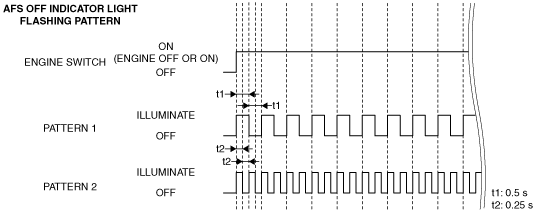
• The AFS control module flashes the AFS OFF light as follows if there is a malfunction in the system.
ac5wzn00001406
|
ON-BOARD DIAGNOSTIC [ADAPTIVE FRONT LIGHTING SYSTEM (AFS)]
id091800693100
Outline
Malfunction detection function
ac5wzn00001406
|
DTC table
|
DTC No. |
AFS OFF indicator light |
Description |
Fail-safe function |
Drive cycle |
Self test type*1 |
Memory function |
|---|---|---|---|---|---|---|
|
B1041:14
|
Flash
(Pattern 1)
|
Headlight leveling actuator circuit malfunction
|
×
|
—
|
D
|
×
|
|
B1041:54
|
Flash
(Pattern 2)
|
Headlight auto leveling system initial setting error
|
×
|
—
|
D
|
×
|
|
B1044:01
|
Flash
(Pattern 1)
|
Auto leveling sensor circuit malfunction
|
×
|
—
|
D
|
×
|
|
B10A3:86
|
Flash
(Pattern 1)
|
Communication error with swivel actuator (LH)
|
×
|
—
|
D
|
×
|
|
B10A3:87
|
Flash
(Pattern 1)
|
Communication error with swivel actuator (LH)
|
×
|
—
|
D
|
×
|
|
B10A4:86
|
Flash
(Pattern 1)
|
Communication error with swivel actuator (RH)
|
×
|
—
|
D
|
×
|
|
B10A4:87
|
Flash
(Pattern 1)
|
Communication error with swivel actuator (RH)
|
×
|
—
|
D
|
×
|
|
C0051:86
|
Flash
(Pattern 1)
|
Error steering angle signal received from EPS control module
|
×
|
—
|
C, D
|
×
|
|
U0001:88
|
Flash
(Pattern 1)
|
Unit communication error (HS-CAN)
|
×
|
—
|
C, D
|
×
|
|
U0100:00
|
Flash
(Pattern 1)
|
Communication error with PCM
|
×
|
—
|
C, D
|
×
|
|
U0131:00
|
Flash
(Pattern 1)
|
Communication error with EPS control module
|
×
|
—
|
C, D
|
×
|
|
U0140:00
|
Flash
(Pattern 1)
|
Communication error with front body control module (FBCM)
|
×
|
—
|
C, D
|
×
|
|
U0155:00
|
Flash
(Pattern 1)
|
Communication error with instrument cluster
|
×
|
—
|
C, D
|
×
|
|
U0320:09
|
Flash
(Pattern 1)
|
EPS control module malfunction
|
×
|
—
|
C, D
|
×
|
|
U0420:68
|
Flash
(Pattern 1)
|
Error signal received from EPS control module
|
×
|
—
|
C, D
|
×
|
|
U0423:68
|
—
|
Error signal received from instrument cluster
• AFS OFF switch error signal
|
×
|
—
|
C, D
|
—
|
|
—
|
Error signal received from instrument cluster
• Ignition switch error signal
|
×
|
—
|
C, D
|
—
|
|
|
Flash
(Pattern 1)
|
Error signal received from instrument cluster
• Selector lever position (R position) (ATX)/Reverse (MTX) signal error
|
×
|
—
|
C, D
|
×
|
|
|
—
|
Error signal received from instrument cluster
• Selector lever position (R position) (ATX)/Reverse (MTX) signal not determined
|
×
|
—
|
C, D
|
—
|
|
|
U2005:86
|
Flash
(Pattern 1)
|
Error signal received from PCM
|
×
|
—
|
C, D
|
×
|
|
U2300:54
|
Flash
(Pattern 1)
|
Error configuration data received from instrument cluster
|
×
|
—
|
C, D
|
×
|
|
U2300:55
|
—
|
Instrument cluster configuration not implemented
|
×
|
—
|
C, D
|
×
|
|
U2300:56
|
Flash
(Pattern 1)
|
Configuration data unmatched with instrument cluster
|
×
|
—
|
C, D
|
×
|
|
U3000:42
|
Flash
(Pattern 1)
|
AFS control module internal malfunction
|
×
|
—
|
C, D
|
×
|
|
U3000:49
|
—
|
AFS control module internal malfunction
• RAM/ROM malfunction
|
×
|
—
|
C, D
|
×
|
|
—
|
AFS control module internal malfunction
• AFS function malfunction
|
—
|
—
|
C, D
|
—
|
|
|
—
|
AFS control module internal malfunction
• CAN hardware malfunction
|
×
|
—
|
C, D
|
×
|
|
|
U3003:16
|
—
|
AFS control module low power supply voltage input
|
×
|
—
|
C, D
|
—
|
|
U3003:17
|
—
|
AFS control module high power supply voltage input
|
×
|
—
|
C, D
|
—
|
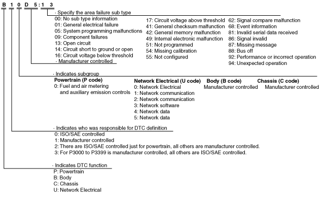
DTC 7-digit code definition
ac5uun00001106
|
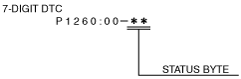
Status byte for DTC
ac5wzn00002013
|
Detection condition for the applicable DTC
|
DTC No. |
System malfunction location |
Detection condition |
|---|---|---|
|
B1041:14
|
Headlight leveling actuator circuit malfunction
|
Headlight leveling actuator circuit voltage of 3.2 V or less is detected for 5 s or more with the ignition switched ON (engine off or on).
|
|
B1041:54
|
Headlight auto leveling system initialization error
|
Ignition is switched ON (engine off or on) and headlight auto leveling system initialization is not performed.
|
|
B1044:01
|
Auto leveling sensor circuit malfunction
|
Auto leveling sensor circuit voltage of 0.25 V or less or 4.75 V or more is detected by AFS control module for 10 s or more with the ignition switched ON (engine off or on).
|
|
B10A3:86
|
Communication error with swivel actuator (LH)
|
• The AFS control module received error signals from the swivel actuator (LH) three times continuously with the ignition switched ON (engine off or on).
• The AFS control module could not receive the signal from the swivel actuator (LH) for 5 s or more with the ignition switched ON (engine off or on).
|
|
B10A3:87
|
Communication error with swivel actuator (LH)
|
The AFS control module detected communication error with the swivel actuator (LH) for 5 s or more with the ignition switched ON (engine off or on).
|
|
B10A4:86
|
Communication error with swivel actuator (RH)
|
• The AFS control module received error signals from the swivel actuator (RH) three times continuously with the ignition switched ON (engine off or on).
• The AFS control module could not receive the signal from the swivel actuator (RH) for 5 s or more with the ignition switched ON (engine off or on).
|
|
B10A4:87
|
Communication error with swivel actuator (RH)
|
The AFS control module detected communication error with the swivel actuator (RH) for 5 s or more with the ignition switched ON (engine off or on).
|
|
C0051:86
|
Error steering angle signal received from EPS control module
|
Either a condition in which the steering angle sensor has a malfunction and the EPS control module has not performed steering angle neutral position auto learning, or a condition in which the EPS control module has a malfunction is detected for 5 s or more.
|
|
U0001:88
|
Unit communication error (HS-CAN)
|
The AFS control module detected CAN bus communication line (HS-CAN) malfunction ten times continuously.
|
|
U0100:00
|
Communication error with PCM
|
The AFS control module could not receive CAN signal from the PCM for 5 s or more.
|
|
U0131:00
|
Communication error with EPS control module
|
The AFS control module could not receive CAN signal from the EPS control module for 5 s or more.
|
|
U0140:00
|
Communication error with front body control module (FBCM)
|
The AFS control module could not receive CAN signal from the front body control module (FBCM) for 5 s or more.
|
|
U0155:00
|
Communication error with instrument cluster
|
The AFS control module could not receive CAN signal from the instrument cluster for 5 s or more.
|
|
U0320:09
|
EPS control module malfunction
|
The AFS control module received CAN error signal from the EPS control module for 5 s or more with the ignition switched ON (engine off or on).
|
|
U0420:68
|
Error signal received from EPS control module
|
The AFS control module received error signal from the EPS control module for 5 s or more with the ignition switched ON (engine off or on).
|
|
U0423:68
|
AFS OFF switch error signal
|
The AFS control module received AFS OFF switch error signal for 5 s or more with the ignition switched ON (engine off or on).
|
|
Ignition switch error signal
|
The AFS control module received ignition switch error signal for 5 s or more with the ignition switched ON (engine off or on).
|
|
|
Selector lever position (R position) (ATX)/Reverse (MTX) signal error
|
The AFS control module received selector lever position (R position) (ATX)/Reverse (MTX) signal error for 5 s or more with the ignition switched ON (engine off or on).
|
|
|
Selector lever position (R position) (ATX)/Reverse (MTX) signal not determined
|
The AFS control module detected undetermined selector lever position (R position) (ATX)/Reverse (MTX) signal.
|
|
|
U2005:86
|
Error signal received from PCM
|
The AFS control module received vehicle speed signal error from the PCM for 5 s or more with the ignition switched ON (engine off or on).
|
|
U2300:54
|
Error configuration data received from instrument cluster
|
The AFS control module received error configuration data from the instrument cluster for 30 s or more with the ignition switched ON (engine off or on).
|
|
U2300:55
|
Instrument cluster configuration not implemented
|
The AFS control module received a signal which indicates the instrument cluster configuration is not performed.
|
|
U2300:56
|
Configuration data unmatched with instrument cluster
|
Configuration data of the AFS control module and instrument cluster are not matched.
|
|
U3000:42
|
AFS control module internal malfunction
|
Malfunction in the AFS control module internal EEPROM is detected.
|
|
U3000:49
|
RAM/ROM malfunction
|
The AFS control module detected a malfunction in the internal RAM/ROM.
|
|
AFS function malfunction
|
The AFS control module detected AFS function malfunction three times.
|
|
|
CAN hardware malfunction
|
The AFS control module detected CAN hardware malfunction three times.
|
|
|
U3003:16
|
AFS control module low power supply voltage input
|
AFS control module power supply circuit voltage of 9 V or less is detected for 5 s or more with the ignition switched ON (engine off or on).
|
|
U3003:17
|
AFS control module high power supply voltage input
|
AFS control module power supply circuit voltage of 18.1 V or more is detected for 5 s or more with the ignition switched ON (engine off or on).
|
Snapshot data
|
Snapshot data item |
Unit |
Data contents |
Data read/use method |
Corresponding data monitor items |
|
|---|---|---|---|---|---|
|
AAT
|
°C
|
°F
|
Ambient temperature
|
—
|
—
|
|
APP_STATUS
|
Accelerator Pedal Off/Under20%/Over20%/FAIL
|
Accelerator pedal position status
|
—
|
—
|
|
|
CFG_STATUS
|
Config Complete/Not Configured/Config Error
|
Instrument cluster configuration status
|
—
|
—
|
|
|
ECT_STATUS
|
Under 0 degrees C/0 - Under 80 degrees C/Over 80 degrees C/FAIL
|
Engine coolant temperature status
|
—
|
—
|
|
|
IC_VPWR
|
V
|
Instrument cluster power supply voltage
|
• The AFS control module constantly receives the power supply voltage value of the instrument cluster sent via CAN signal from the instrument cluster.
• If a DTC is detected, the AFS control module records the power supply voltage of the instrument cluster when the DTC was detected, and it is displayed in the M-MDS.
|
VPWR*1
|
|
|
IG-ON_TIMER
|
hh:mm:ss*2
|
Elapsed time since ignition was switched ON (engine off or on)
|
• The AFS control module constantly receives the elapsed time since the ignition was switched ON (engine off or on) sent via CAN signal from the instrument cluster.
• If a DTC is detected, the AFS control module records the elapsed time since the ignition was switched ON (engine off or on) when the DTC was detected, and it is displayed in the M-MDS.
|
—
|
|
|
PWR_MODE_KEY
|
Key Out/Key Recently Out (Position 0)/Accessory (Position 1)/Post Ignition (Position 2)/Ignition On (Position 2)/Running (Position 2)/Running - Starting
|
• Key Out: Ignition switched off
• Key Recently Out (Position 0): Elapsed time within 3 s since ignition was switched off
• Accessory (Position 1): Ignition is switched to ACC
• Post Ignition (Position 2): Elapsed time within 3 s since ignition was switched ON (engine off or on)
• Ignition On (Position 2): Ignition switched ON (engine off)
• Running (Position 2): Ignition switched ON (engine on)
• Running - Starting: Cranking condition
|
• The AFS control module constantly receives the ignition switch status sent via CAN signal from the instrument cluster.
• If a DTC is detected, the AFS control module records the ignition switch status when the DTC was detected, and it is displayed in the M-MDS.
|
—
|
|
|
RPM_STATUS
|
Engine Stop/Under1500rpm/Over1500rpm/FAIL
|
Engine speed status
|
• The AFS control module constantly receives the engine speed sent via CAN signal from the instrument cluster.
• If a DTC is detected, the AFS control module records the engine speed when the DTC was detected, and it is displayed in the M-MDS.
|
TACHOMTR*1
|
|
|
SHIFT_STATUS
|
P/N/D/R/FAIL
|
Selector lever position status
|
• The AFS control module constantly receives the selector lever position sent via CAN signal from the instrument cluster.
• If a DTC is detected, the AFS control module records the selector lever position when the DTC was detected, and it is displayed in the M-MDS.
|
—
|
|
|
TOTAL_DIST
|
km
|
Miles
|
Accumulated total traveled distance from completion of vehicle until AFS control module detects DTC (Odometer value in instrument cluster)
|
The total traveled distance from which the AFS control module detects DTCs to the present can be calculated by performing the following procedure.
1. Verify the odometer value in the instrument cluster.
2. Verify the snapshot data item TOTAL_DIST.
3. Subtract 2 from 1.
|
—
|
|
TOTAL_TIME
|
hh:mm:ss*2
|
Accumulated total elapsed time since vehicle completion until AFS control module detects a DTC
|
The elapsed time from which the AFS control module detects DTCs to the present can be calculated by performing the following procedure.
1. Verify the instrument cluster PID item TOTAL_TIME.
2. Verify the snapshot data item TOTAL_TIME.
3. Subtract 2 from 1.
|
TOTAL_TIME*1
|
|
|
VPWR
|
V
|
AFS control module power supply voltage
|
—
|
VPWR_IG
|
|
|
VSPD_STATUS
|
Stop/0-10km/h/Over10km/h/FAIL
|
Vehicle speed status
|
• The AFS control module constantly receives the vehicle speed sent via CAN signal from the instrument cluster.
• If a DTC is detected, the AFS control module records the vehicle speed when the DTC was detected, and it is displayed in the M-MDS.
|
SPEEDOMTR*1
|
|
Data Monitor Function
PID/data monitor table
|
PID |
Unit/Operation |
Data contents |
Inspection item(s) |
|---|---|---|---|
|
AFS_ST
|
Off/On
|
• Off: AFS is not operated
• On: AFS is operated
|
• AFS OFF switch
• AFS control module
|
|
H/L_CS
|
OFF/DRL/TNS/H/L_LOW/H/L_HI
|
• OFF: Light switch at OFF position
• DRL: Light switch at AUTO position and auto light sensor sends turn-off signal
• TNS: Light switch at TNS position
• H/L_LOW: Light switch at LO position
• H/L_HI: Light switch at HI position
|
Light switch
|
|
R_HGT_S
|
V
|
Voltage at auto leveling sensor is displayed.
|
Auto leveling sensor
|
|
R_HGT_S_INI
|
V
|
Voltage at headlight auto leveling system initial setting is displayed.
|
Auto leveling sensor
|
|
R_LMP_CS
|
Off/On/Unknown/Fault
|
ATX:
• Off: Selector lever position signal (R position) is not received
• On: Selector lever position signal (R position) is received
• Unknown: Selector lever position signal (R position) is not determined
• Fault: Selector lever position signal (R position) error is received
MTX:
• Off: Reverse signal is not received
• On: Reverse signal is received
• Unknown: Reverse signal is not determined
• Fault: Reverse signal error is received
|
ATX:
• Transaxle range sensor (TCM)
MTX:
• Back-up light switch
|
|
STR_AB_ANG
|
° (deg)
|
Displays steering angle signal (estimated absolute angle)
• Steering wheel in neutral position: Near 0 degrees
• Steering wheel turned to left: Changes from 0 degrees to positive
• Steering wheel turned to right: Changes from 0 degrees to negative
|
• Perform the DTC inspection for the PCM, DSC HU/CM, and EPS CM, and if any DTC is displayed, repair the malfunctioning part according to the applicable DTC troubleshooting.
• After performing the DTC inspection, perform the following procedures:
• If an abnormal value is indicated again, replace the EPS CM.
|
|
VPWR_IG
|
V
|
AFS control module power supply voltage is displayed.
|
• AFS control module
• IG1 relay
• Battery
|
|
VSPD
|
KPH, MPH
|
Vehicle speed is displayed.
|
—
|