|
ac5wzw00001208
IGNITER REMOVAL/INSTALLATION
id091800814200
Igniter (LH)
1. Disconnect the negative battery cable. (See NEGATIVE BATTERY CABLE DISCONNECTION/CONNECTION [SKYACTIV-G 2.0, SKYACTIV-G 2.5].) (See NEGATIVE BATTERY CABLE DISCONNECTION/CONNECTION [SKYACTIV-G 2.0, SKYACTIV-G 2.5 (WITHOUT i-stop)].) (See NEGATIVE BATTERY CABLE DISCONNECTION/CONNECTION [SKYACTIV-D 2.2].)
2. Remove the air cleaner cover. (See INTAKE-AIR SYSTEM REMOVAL/INSTALLATION [SKYACTIV-G 2.0, SKYACTIV-G 2.5].) (See INTAKE-AIR SYSTEM REMOVAL/INSTALLATION [SKYACTIV-D 2.2].)
3. Remove the relay and fuse block upper cover. (See RELAY AND FUSE BLOCK REMOVAL/INSTALLATION.)
4. Remove the nut and screw.
ac5wzw00001208
|
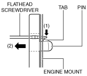
5. Insert a tape-wrapped flathead screwdriver into the service hole in the position shown in the figure.
ac5wzw00000502
|
6. While pressing the pin tab in the direction of the arrow (1) shown in the figure using a flathead screwdriver, pull the pin in the direction of the arrow (2) shown in the figure to detach the pin tab and engine mount.
ac5wzw00001209
|
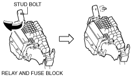
7. Pull out the relay and fuse block from the stud bolt and set it aside as shown in the figure.
ac5wzw00000504
|
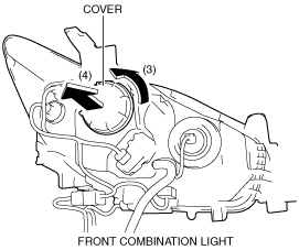
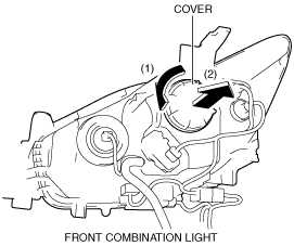
8. Rotate the cover in the direction of the arrow (3) shown in the figure and remove it from the front combination light in the direction of the arrow (4) shown in the figure.
ac5wzw00000505
|
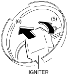
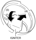
9. Rotate the igniter in the direction of the arrow (5) shown in the figure and remove it from the front combination light in the direction of the arrow (6) shown in the figure.
ac5wzw00000506
|
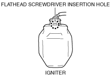
10. Insert the flathead screwdriver into the gap between the igniter and connector shown in the figure.
ac5wzw00001210
|
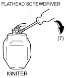
11. Move the flathead screwdriver in the direction of the arrow (7) shown in the figure, lift up the connector, and disconnect it.
ac5wzw00000508
|
12. Install in the reverse order of removal.
Igniter (RH)
1. Remove the PCM bracket. (SKYACTIV-D 2.2) (See PCM REMOVAL/INSTALLATION [SKYACTIV-D 2.2].)
2. Remove the washer tank bracket. (See WASHER TANK REMOVAL/INSTALLATION.)
3. Rotate the cover in the direction of the arrow (1) shown in the figure and remove it from the front combination light in the direction of the arrow (2) shown in the figure.
ac5wzw00003015
|
4. Rotate the igniter in the direction of the arrow (3) shown in the figure and remove it from the front combination light in the direction of the arrow (4) shown in the figure.
ac5wzw00003016
|
5. Insert the flathead screwdriver into the gap between the igniter and connector shown in the figure.
ac5wzw00001210
|
6. Move the flathead screwdriver in the direction of the arrow (5) shown in the figure, lift up the connector, and disconnect it.
ac5wzw00000830
|
7. Install in the reverse order of removal.