DETERMINING OPEN CIRCUIT LOCATION (MS-CAN) [SKYACTIV-G 2.0, SKYACTIV-G 2.5 (L.H.D.)]
id100208000500
-
Caution
-
• If the malfunctioning part is detected in the communication line, before disconnecting the related connector for inspection, press the connector in the connection direction to verify that there is no looseness or disconnection.
• When disconnecting the connector, verify that there is no damage, deformation, or corrosion of the connector terminals.
1. Verify DTCs of the modules related to the CAN system.
2. Apply the communication error DTC and the failed module to DTC Output Pattern And Malfunctioning Location, and select the possible cause for the diagnostic result and the reference for the inspection item. (See DTC Output Pattern And Malfunctioning Location.)
-
Note
-
• The open circuit location can be determined by the DTC indicated in the DTC Output Pattern And Malfunctioning Location chart. DTCs not listed in the chart are not used for the determination of the open circuit location. (See
DTC Output Pattern And Malfunctioning Location.)
3. Inspect the possible cause and inspection item of the applicable malfunctioning part.
4. After repairs, return to CONTROLLER AREA NETWORK (CAN) MALFUNCTION DIAGNOSIS FLOW [SKYACTIV-G 2.0, SKYACTIV-G 2.5 (L.H.D.)], and verify that the repairs have been completed. (See CONTROLLER AREA NETWORK (CAN) MALFUNCTION DIAGNOSIS FLOW [SKYACTIV-G 2.0, SKYACTIV-G 2.5 (L.H.D.)].)
DTC Output Pattern And Malfunctioning Location
Cross (×): Displayed
|
M-MDS display
|
DTC output pattern and malfunctioning location
|
|
DTC output module
|
DTC
|
|
R_BCM
(Rear body control module (RBCM))
|
U0155:00
|
|
|
|
|
|
|
×
|
|
|
RVM*1
(Rear vehicle monitoring control module (RH))
|
U0100:00
|
|
|
|
|
|
|
×
|
|
|
U0121:00
|
|
|
|
|
|
|
×
|
|
|
U0155:00
|
|
|
|
|
|
|
×
|
|
|
U0214:00
|
|
|
|
|
|
|
×
|
|
|
EATC*2
(Climate control unit)
|
U0155:00
|
|
|
|
|
|
|
×
|
|
|
ACU*3
(Audio unit)
|
U0155:00
|
|
|
|
|
|
|
×
|
|
|
IC
(Instrument cluster)
|
U0142:00
|
×
|
×
|
|
×
|
|
|
|
|
|
U0232:00
|
|
|
×
|
×
|
|
|
|
|
|
M-MDS display module
|
[Fail] display pattern
|
|
R_BCM
|
×
|
×
|
|
×
|
|
|
|
|
|
RVM*1
|
|
|
×
|
×
|
|
|
|
|
|
EATC*2
|
|
|
|
|
×
|
|
|
|
|
ACU*3
|
|
|
|
|
|
×
|
|
|
|
IC
|
|
|
|
|
|
|
×
|
|
|
Diagnostic result
|
|
Possible cause and inspection item
|
|
|
|
|
|
|
|
|
*1 :With rear vehicle monitoring system
*2 :With full-auto air conditioner
*3 :With audio unit
A
Possible cause
-
• Connector terminal disconnection, poor contact, damage, deformation, corrosion
• Rear body control module (RBCM) malfunction
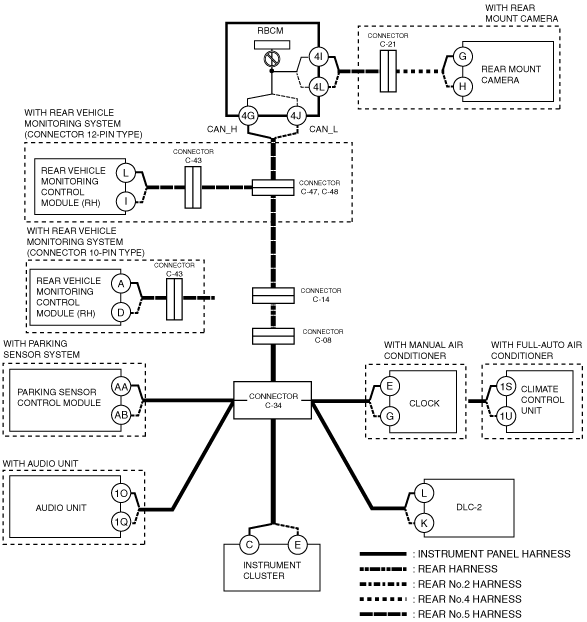
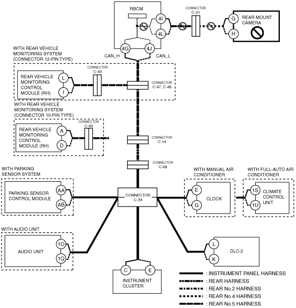
System wiring diagram
Inspection item
-
• Rear body control module (RBCM)
B
With rear vehicle monitoring system
-
Possible cause
-
• Connector terminal disconnection, poor contact, damage, deformation, corrosion
• Open circuit in wiring harness between rear body control module (RBCM) and connectors C-47, C-48
• Connector C-47, C-48 malfunction
• CAN circuit in rear body control module (RBCM) malfunction
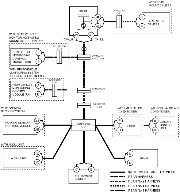
System wiring diagram
-
Inspection item
-
• Rear body control module (RBCM) connector
• Connectors C-47, C-48
• Wiring harness between rear body control module (RBCM) terminal 4G and connectors C-47
• Wiring harness between rear body control module (RBCM) terminal 4J and connectors C-48
• Rear body control module (RBCM)
-
― Wiring harness between rear body control module (RBCM) terminal 4G and rear body control module (RBCM) terminal 4I
― Wiring harness between rear body control module (RBCM) terminal 4J and rear body control module (RBCM) terminal 4L
Without rear vehicle monitoring system
-
Possible cause
-
• Connector terminal disconnection, poor contact, damage, deformation, corrosion
• Open circuit in wiring harness between rear body control module (RBCM) and connector C-14
• Open circuit in wiring harness between connector C-14 and connector C-08
• Open circuit in wiring harness between connector C-08 and connector C-34
• Connector C-14 malfunction
• Connector C-08 malfunction
• Connector C-34 malfunction
• Rear body control module (RBCM) malfunction
System wiring diagram
-
Inspection item
-
• Rear body control module (RBCM) connector
• Connector C-14
• Connector C-08
• Connector C-34
• Wiring harness between rear body control module (RBCM) terminal 4G and connector C-14
• Wiring harness between rear body control module (RBCM) terminal 4J and connector C-14
• Wiring harness between connector C-14 and connector C-08
• Wiring harness between connector C-08 and connector C-34
• Rear body control module (RBCM)
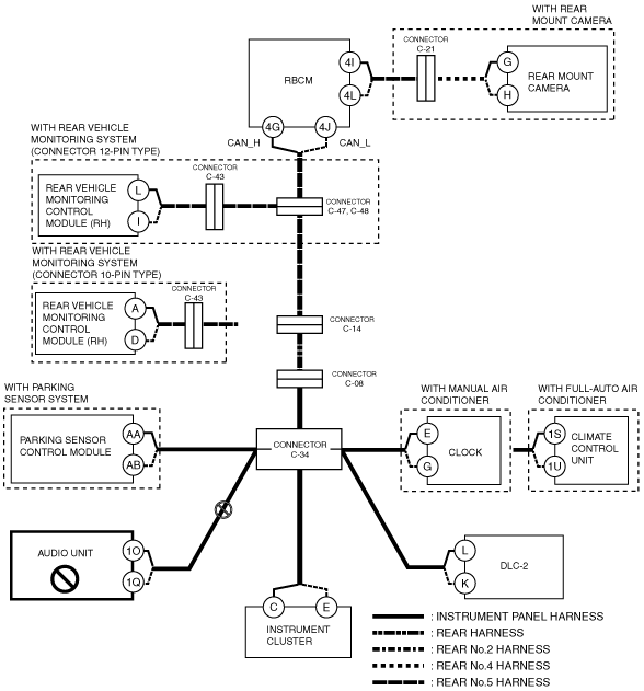
C
Possible cause
-
• Connector terminal disconnection, poor contact, damage, deformation, corrosion
• Open circuit in wiring harness between rear vehicle monitoring (RH) and connectors C-43
• Open circuit in wiring harness between connectors C-43 and connectors C-47, C-48
• Connector C-43 malfunction
• Connector C-47, C-48 malfunction
• Rear vehicle monitoring control module (RH) malfunction
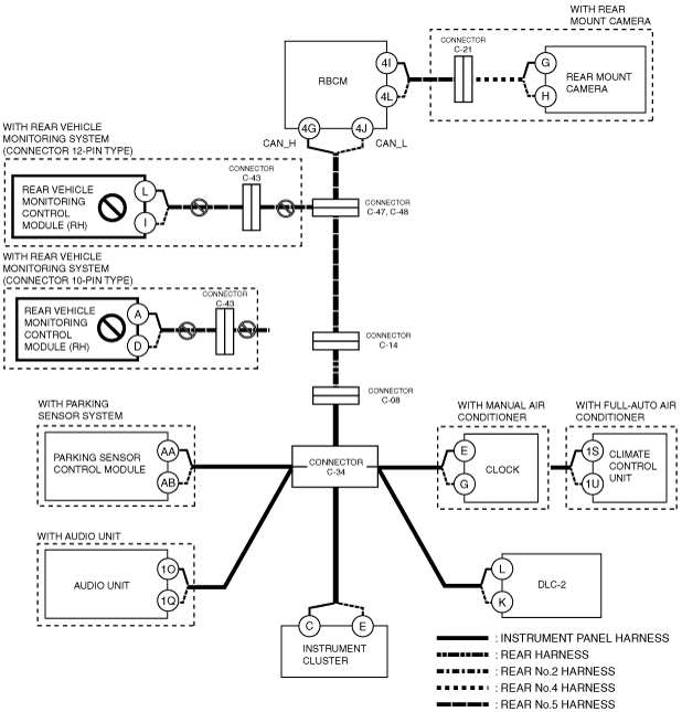
System wiring diagram
Inspection item
-
• Rear vehicle monitoring control module (RH) connector
• Connectors C-43
• Connectors C-47, C-48
• Wiring harness between Rear vehicle monitoring control module (RH) terminal L and connector C-43 (connector 12-pin type)
• Wiring harness between Rear vehicle monitoring control module (RH) terminal I and connector C-43 (connector 12-pin type)
• Wiring harness between Rear vehicle monitoring control module (RH) terminal A and connector C-43 (connector 10-pin type)
• Wiring harness between Rear vehicle monitoring control module (RH) terminal D and connector C-43 (connector 10-pin type)
• Wiring harness between connector C-43 and connector C-47, C-48
• Rear vehicle monitoring control module (RH)
D
Possible cause
-
• Connector terminal disconnection, poor contact, damage, deformation, corrosion
• Open circuit in wiring harness between connectors C-47, C-48 and connector C-14
• Open circuit in wiring harness between connector C-14 and C-08
• Open circuit in wiring harness between connectors C-08 and C-34
• Connectors C-47, C-48 malfunction
• Connector C-14 malfunction
• Connector C-08 malfunction
• Connector C-34 malfunction
System wiring diagram
Inspection item
-
• Connectors C-47, C-48
• Connector C-14
• Connector C-08
• Connector C-34
• Wiring harness between connectors C-47, C-48 and connector C-14
• Wiring harness between connector C-14 and connector C-08
• Wiring harness between connector C-08 and connector C-34
E
Possible cause
-
• Connector terminal disconnection, poor contact, damage, deformation, corrosion
• Open circuit in wiring harness between climate control unit and connector C-34
• Connector C-34 malfunction
• Climate control unit malfunction
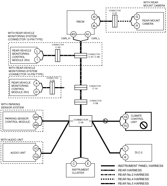
System wiring diagram
Inspection item
-
• Climate control unit connector
• Connector C-34
• Wiring harness between climate control unit terminal 1S and connector C-34
• Wiring harness between climate control unit terminal 1U and connector C-34
• Climate control unit
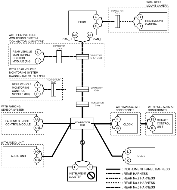
F
Possible cause
-
• Connector terminal disconnection, poor contact, damage, deformation, corrosion
• Open circuit in wiring harness between vehicle with audio unit and connector C-34
• Connector C-34 malfunction
• Audio unit malfunction
System wiring diagram
Inspection item
-
• Audio unit connector
• Connector C-34
• Wiring harness between audio unit terminal 1O and connector C-34
• Wiring harness between audio unit terminal 1Q and connector C-34
• Audio unit
G
Possible cause
-
• Connector terminal disconnection, poor contact, damage, deformation, corrosion
• Open circuit in wiring harness between instrument cluster and connector C-34
• Connector C-34 malfunction
• Instrument cluster malfunction
System wiring diagram
Inspection item
-
• Instrument cluster connector
• Connector C-34
• Wiring harness between instrument cluster terminal C and connector C-34
• Wiring harness between instrument cluster terminal E and connector C-34
• Instrument cluster
H
1. Perform the clock input/output check mode. (See CLOCK INPUT/OUTPUT CHECK MODE.)
-
• If "2:00" is displayed, go to the next step.
2. Shift the selector lever (ATX) or shift lever (MTX) to the R position.
-
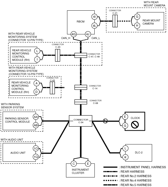
Clock Circuit Malfunction
-
Possible cause
-
• Connector terminal disconnection, poor contact, damage, deformation, corrosion
• Open circuit in wiring harness between clock component and connector C-34
• Connector C-34 malfunction
• Clock component malfunction
System wiring diagram
-
Inspection item
-
• Clock component connector
• Connector C-34
• Wiring harness between clock component terminal E and connector C-34
• Wiring harness between clock component terminal G and connector C-34
• Clock component
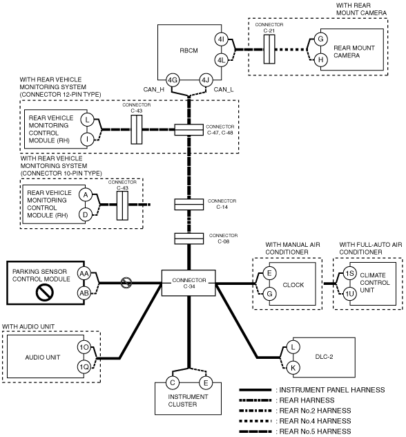
Parking Sensor Control Module Circuit Malfunction
-
Possible cause
-
• Connector terminal disconnection, poor contact, damage, deformation, corrosion
• Open circuit in wiring harness between parking sensor control module and connector C-34
• Connector C-34 malfunction
• Parking sensor control module malfunction
System wiring diagram
-
Inspection item
-
• Parking sensor control module connector
• Connector C-34
• Wiring harness between parking sensor control module terminal AA and connector C-34
• Wiring harness between parking sensor control module terminal AB and connector C-34
• Parking sensor control module
Rear Mount Camera Circuit Malfunction
-
Possible cause
-
• Connector terminal disconnection, poor contact, damage, deformation, corrosion
• Open circuit in wiring harness between rear mount camera and connector C-21
• Open circuit in wiring harness between connector C-21 and RCBM
• Connector C-21 malfunction
• Rear mount camera malfunction
• CAN circuit in rear body control module (RBCM) malfunction
System wiring diagram
-
Inspection item
-
• Rear mount camera connector
• Connector C-21
• Wiring harness between rear mount camera terminal G and connector C-21.
• Wiring harness between rear mount camera terminal H and connector C-21.
• Wiring harness between rear body control module (RBCM) terminal 4I and connector C-21
• Wiring harness between rear body control module (RBCM) terminal 4L and connector C-21
• Rear mount camera
• Rear body control module (RBCM)
-
― Between rear body control module (RBCM) terminal 4G and rear body control module (RBCM) terminal 4I
― Between rear body control module (RBCM) terminal 4J and rear body control module (RBCM) terminal 4L