 |
ac5wzw00000683
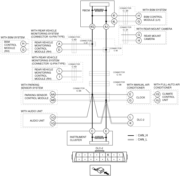
DETERMINING SHORT TO GROUND LOCATION (MS-CAN) [SKYACTIV-G 2.0, SKYACTIV-G 2.5 (R.H.D.)]
id100209000900
System Wiring Diagram
ac5wzw00000683
|
Determination Procedure
|
Step |
Inspection |
Action |
|
|---|---|---|---|
|
1
|
INSPECT FOR SHORT TO GROUND BETWEEN CONNECTOR C-08 AND INSTRUMENT CLUSTER
• Disconnect the negative battery cable.
• Disconnect connector C-08.
• Inspect for continuity at the following terminals:
• Is there continuity?
|
Yes
|
Go to the next step.
|
|
No
|
Go to Step 11.
|
||
|
2
|
INSPECT FOR SHORT TO GROUND BETWEEN CONNECTORS C-34 AND DLC-2
• Disconnect connector C-34.
• Inspect for continuity at the following terminals:
• Is there continuity?
|
Yes
|
Repair or replace the wiring harness between connector C-34 and DLC-2 because the wiring harness is shorted to ground.
|
|
No
|
Go to the next step.
|
||
|
3
|
INSPECT FOR SHORT TO GROUND BETWEEN CONNECTOR C-34 AND PARKING SENSOR CONTROL MODULE
• Inspect for continuity at the following terminals:
• Is there continuity?
|
Yes
|
Go to the next step.
|
|
No
|
Go to Step 5.
|
||
|
4
|
INSPECT CAN LINE IN PARKING SENSOR CONTROL MODULE FOR SHORT TO GROUND
• Disconnect the parking sensor connector.
• Inspect for continuity at the following terminals:
• Is there continuity?
|
Yes
|
Repair or replace the wiring harness between the parking sensor control module and connector C-34 because the wiring harness is shorted to ground.
|
|
No
|
Replace the parking sensor control module because there is a short to ground in the parking sensor control module.
|
||
|
5
|
INSPECT FOR SHORT TO GROUND BETWEEN CONNECTOR C-34 AND CLIMATE CONTROL UNIT
• Inspect for continuity at the following terminals:
• Is there continuity?
|
Yes
|
Go to the next step.
|
|
No
|
Go to Step 7.
|
||
|
6
|
INSPECT CAN LINE IN CLIMATE CONTROL UNIT OR CLOCK FOR SHORT TO GROUND
• Disconnect the climate control unit connector or clock connector.
• Inspect for continuity at the following terminals:
• Is there continuity?
|
Yes
|
Repair or replace the wiring harness between the climate control unit or clock and connector C-34 because the wiring harness is shorted to ground.
|
|
No
|
Replace the climate control unit or the clock because there is a short to ground inside the climate control unit or the clock.
(See CLOCK REMOVAL/INSTALLATION.)
|
||
|
7
|
INSPECT FOR SHORT TO GROUND BETWEEN CONNECTOR C-34 AND AUDIO UNIT
• Inspect for continuity at the following terminals:
• Is there continuity?
|
Yes
|
Go to the next step.
|
|
No
|
Go to Step 9.
|
||
|
8
|
INSPECT CAN LINE IN AUDIO UNIT FOR SHORT TO GROUND
• Disconnect the audio unit connector.
• Inspect for continuity at the following terminals:
• Is there continuity?
|
Yes
|
Repair or replace the wiring harness between the audio unit and connector C-34 because the wiring harness is shorted to ground.
|
|
No
|
Replace the audio unit because there is a short to ground in the audio unit.
|
||
|
9
|
INSPECT FOR SHORT TO GROUND BETWEEN CONNECTOR C-34 AND INSTRUMENT CLUSTER
• Inspect for continuity at the following terminals:
• Is there continuity?
|
Yes
|
Go to the next step.
|
|
No
|
Repair or replace the wiring harness between connectors C-08 and C-34 because the wiring harness is shorted to ground.
|
||
|
10
|
INSPECT CAN LINE IN INSTRUMENT CLUSTER FOR SHORT TO GROUND
• Disconnect the instrument cluster connector.
• Inspect for continuity at the following terminals:
• Is there continuity?
|
Yes
|
Repair or replace the wiring harness between the instrument cluster and connector C-34 because the wiring harness is shorted to ground.
|
|
No
|
Replace the instrument cluster because there is a short to ground in the instrument cluster.
|
||
|
11
|
INSPECT FOR SHORT TO GROUND BETWEEN CONNECTORS C-14 AND C-08
• Disconnect connector C-14.
• Connect connector C-08.
• Inspect for continuity at the following terminals:
• Is there continuity?
|
Yes
|
Repair or replace the wiring harness between connectors C-14 and C-08 because the wiring harness is shorted to ground.
|
|
No
|
Go to the next step.
|
||
|
12
|
INSPECT FOR SHORT TO GROUND BETWEEN CONNECTOR C-14 AND CONNECTORS C-47 AND C-48
• Disconnect connectors C-47 and C-48.
• Connect connector C-14.
• Inspect for continuity at the following terminals:
• Is there continuity?
|
Yes
|
Repair or replace the wiring harness between connectors C-47 and C-48 and connector C-14 because the wiring harness is shorted to ground.
|
|
No
|
Go to the next step.
|
||
|
13
|
INSPECT FOR SHORT TO GROUND BETWEEN REAR VEHICLE MONITORING CONTROL MODULE (RH) OR BSM CONTROL MODULE (RH) AND CONNECTORS C-47 AND C-48
• Inspect for continuity at the following terminals:
• Is there continuity?
|
Yes
|
• Go to the next step. (With rear vehicle monitoring system)
• Go to Step 15. (With BSM system)
|
|
No
|
Go to Step 16.
|
||
|
14
|
INSPECT FOR SHORT TO GROUND BETWEEN REAR VEHICLE MONITORING CONTROL MODULE (RH) AND CONNECTOR C-43
• Disconnect connector C-43.
• Inspect for continuity at the following terminals:
• Is there continuity?
|
Yes
|
Go to the next step.
|
|
No
|
Repair or replace the wiring harness between connector C-43 and connectors C-47 and C-48 because the wiring harness is shorted to ground.
|
||
|
15
|
INSPECT CAN LINE IN REAR VEHICLE MONITORING CONTROL MODULE (RH) OR BSM CONTROL MODULE (RH) FOR SHORT TO GROUND
• Disconnect the rear vehicle monitoring control module (RH) connector or BSM control module (RH) connector.
• Inspect for continuity at the following terminals:
• Is there continuity?
|
Yes
|
• Repair or replace the wiring harness between the rear vehicle monitoring control module (RH) and connector C-43 because the wiring harness is shorted to ground. (With rear vehicle monitoring system)
• Repair or replace the wiring harness between the BSM control module (RH) and connectors C-47 and C-48 because the wiring harness is shorted to ground. (With BSM system)
|
|
No
|
Replace the rear vehicle monitoring control module (RH) or the BSM control module (RH) because there is a short to ground in the rear vehicle monitoring control module (RH) or the BSM control module (RH).
|
||
|
16
|
INSPECT FOR SHORT TO GROUND BETWEEN REAR BODY CONTROL MODULE (RBCM) AND BSM CONTROL MODULE (LH) OR REAR MOUNT CAMERA
• Disconnect the rear body control module (RBCM) connector.
• Inspect for continuity at the following terminals:
• Is there continuity?
|
Yes
|
Go to the next step.
|
|
No
|
Go to Step 19.
|
||
|
17
|
INSPECT FOR SHORT TO GROUND BETWEEN REAR BODY CONTROL MODULE (RBCM) AND CONNECTOR C-23 OR C-21
• Disconnect connector C-23 or C-21.
• Inspect for continuity at the following terminals:
• Is there continuity?
|
Yes
|
Repair or replace the wiring harness between the rear body control module (RBCM) and connector C-23 or C-21 because the wiring harness is shorted to ground.
|
|
No
|
Go to the next step.
|
||
|
18
|
INSPECT CAN LINE IN BSM CONTROL MODULE (LH) OR REAR MOUNT CAMERA FOR SHORT TO GROUND
• Disconnect the BSM control module (LH) connector or the rear mount camera connector.
• Inspect for continuity at the following terminals:
• Is there continuity?
|
Yes
|
• Repair or replace the wiring harness between BSM control module (LH) and connector C-23 because the wiring harness is shorted to ground. (With BSM system)
• Repair or replace the wiring harness between the rear mount camera and connector C-21 because the wiring harness is shorted to ground. (With rear mount camera)
|
|
No
|
Replace the BSM control module (LH) or the rear mount camera because there is a short to ground in the BSM control module (LH) or the rear mount camera.
|
||
|
19
|
INSPECT CAN LINE INSIDE REAR BODY CONTROL MODULE (RBCM) FOR SHORT TO GROUND
• Disconnect the rear body control module (RBCM) connector.
• Inspect for continuity at the following terminals:
• Is there continuity?
|
Yes
|
Repair or replace the wiring harness between the rear body control module (RBCM) and connectors C-47 and C-48 because the wiring harness is shorted to ground.
|
|
No
|
Replace the rear body control module (RBCM) because there is a short to ground in the rear body control module (RBCM).
|
||