|
1
|
RECORD VEHICLE STATUS WHEN DTC WAS DETECTED TO UTILIZE WITH REPEATABILITY VERIFICATION
-
Note
-
• Recording can be facilitated using the screen capture function of the PC.
• Record the freeze frame data/snap shot data.
|
—
|
Go to the next step.
|
|
2
|
INSPECT EGR COOLER BYPASS VALVE/EGR COOLER BYPASS VALVE POSITION SENSOR CONNECTOR CONDITION
• Switch the ignition OFF.
• Disconnect the EGR cooler bypass valve/EGR cooler bypass valve position sensor connector.
• Inspect the connector engagement and connection condition, and inspect the terminals for damage, deformation, corrosion, or disconnection.
• Is the connector normal?
|
Yes
|
Go to the next step.
|
|
No
|
Repair or replace the connector, then go to Step 10.
|
|
3
|
INSPECT PCM CONNECTOR CONDITION
• Disconnect the PCM connector.
• Inspect the connector engagement and connection condition, and inspect the terminals for damage, deformation, corrosion, or disconnection.
• Is the connector normal?
|
Yes
|
Go to the next step.
|
|
No
|
Repair or replace the connector, then go to Step 10.
|
|
4
|
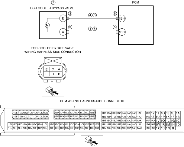
INSPECT EGR COOLER BYPASS VALVE CIRCUIT FOR SHORT TO GROUND
• Verify that the EGR cooler bypass valve/EGR cooler bypass valve position sensor connector is disconnected.
• Inspect for continuity between the following terminals (vehicle wiring harness side) and ground.
-
― EGR cooler bypass valve/EGR cooler bypass valve position sensor terminal E
― EGR cooler bypass valve/EGR cooler bypass valve position sensor terminal A
• Is there continuity?
|
Yes
|
Refer to the wiring diagram and verify if there is a common connector between the following terminals.
• EGR cooler bypass valve/EGR cooler bypass valve position sensor terminal E and PCM terminal 1BH
• EGR cooler bypass valve/EGR cooler bypass valve position sensor terminal A and PCM terminal 1BC
If there is a common connector:
-
― Inspect the common connector and terminals for corrosion, damage, or disconnection and the common wiring harnesses for short to ground to determine the malfunctioning location.
― Repair or replace the malfunctioning location.
If there is no common connector:
-
― Repair or replace the wiring harness which is shorted to ground.
Go to Step 10.
|
|
No
|
Go to the next step.
|
|
5
|
INSPECT EGR VALVE CIRCUIT FOR SHORT TO POWER SUPPLY
• Verify that the EGR cooler bypass valve/EGR cooler bypass valve position sensor connector and the PCM connector are disconnected.
• Switch the ignition ON (engine off).
• Measure the voltage at the following terminals (vehicle wiring harness side).
-
― EGR cooler bypass valve/EGR cooler bypass valve position sensor terminal E
― EGR cooler bypass valve/EGR cooler bypass valve position sensor terminal A
• Is the voltage 0 V?
|
Yes
|
Go to the next step.
|
|
No
|
Refer to the wiring diagram and verify if there is a common connector between the following terminals.
• EGR cooler bypass valve/EGR cooler bypass valve position sensor terminal E and PCM terminal 1BH
• EGR cooler bypass valve/EGR cooler bypass valve position sensor terminal A and PCM terminal 1BC
If there is a common connector:
-
― Inspect the common connector and terminals for corrosion, damage, or disconnection and the common wiring harnesses for short to power supply to determine the malfunctioning location.
― Repair or replace the malfunctioning location.
If there is no common connector:
-
― Repair or replace the wiring harness which is shorted to the power supply.
Go to Step 10.
|
|
6
|
EGR COOLER BYPASS VALVE INSPECTION
• Inspect the EGR cooler bypass valve.
• Is the EGR cooler bypass valve normal?
|
Yes
|
Go to the next step.
|
|
No
|
Replace the EGR cooler bypass valve, then go to the next step.
|
|
7
|
INSPECT COOLER BYPASS VALVE CONTROL
• Using the simulation function, change the EGR_C_BP value (%) and verify that the EGR_C_BP_ACT values comply.
• Does the EGR_C_BP_ACT value comply?
|
Yes
|
Go to the next step.
|
|
No
|
Replace the EGR cooler bypass valve, then go to the next step.
|
|
8
|
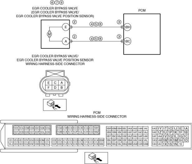
INSPECT EGR COOLER BYPASS VALVE CIRCUIT FOR OPEN CIRCUIT
• Verify that the EGR cooler bypass valve/EGR cooler bypass valve position sensor connector and the PCM connector are disconnected.
• Switch the ignition OFF.
• Inspect the wiring harness for continuity between the following terminals (vehicle wiring harness side).
-
― EGR cooler bypass valve/EGR cooler bypass valve position sensor terminal E and PCM terminal 1BH
― EGR cooler bypass valve/EGR cooler bypass valve position sensor terminal A and PCM terminal 1BC
• Is there continuity?
|
Yes
|
Go to the next step.
|
|
No
|
Refer to the wiring diagram and verify if there is a common connector between the following terminals.
• EGR cooler bypass valve/EGR cooler bypass valve position sensor terminal E and PCM terminal 1BH
• EGR cooler bypass valve/EGR cooler bypass valve position sensor terminal A and PCM terminal 1BC
If there is a common connector:
-
― Inspect the common connector and terminals for corrosion, damage, or disconnection and the common wiring harnesses for an open circuit to determine the malfunctioning location.
― Repair or replace the malfunctioning location.
If there is no common connector:
-
― Repair or replace the wiring harness which has an open circuit.
Go to Step 10.
|
|
9
|
INSPECT EGR COOLER BYPASS VALVE POSITION SENSOR
• Reconnect all the disconnected connectors.
• Inspect the EGR cooler bypass valve position sensor.
• Is the EGR cooler bypass valve position sensor normal?
|
Yes
|
Go to the next step.
|
|
No
|
Replace the EGR cooler bypass valve, then go to the next step.
|
|
10
|
VERIFY THAT REPAIRS HAVE BEEN COMPLETED
• Reconnect all the disconnected connectors.
• Refer to the [MEMORY CLEARING PROCEDURE] and clear the DTC.
• Start the engine and drive the vehicle under the freeze frame data (mode 2)/snapshot data condition.
-
Warning
-
• To prevent an accident, work with another person when the vehicle is being driven (one person drives vehicle, other person operates M-MDS).
• Observe legal speed limits when driving the vehicle and perform the procedure in a location where safety can be assured.
• Display the DTCs using the M-MDS.
• Has DTC P245A:00 been recorded?
|
Yes
|
Repeat the inspection from Step 1.
• If the malfunction recurs, replace the PCM, then go to the next step.
|
|
No
|
Go to the next step.
|
|
11
|
VERIFY OTHER DTCs
• Has any other DTC or pending code been stored?
|
Yes
|
Repair the malfunctioning location according to the applicable DTC troubleshooting.
|
|
No
|
DTC troubleshooting completed.
|