 |
atrizt00000057
DTC P2456:00 [PCM (SKYACTIV-D 2.2)]
id0102j5154000
Engine Type
|
Item |
Reference |
|---|---|
|
Fuel injector (2 pin type)
|
(See Fuel injector (2 pin type).)
|
|
Fuel injector (6 pin type)
|
(See Fuel injector (6 pin type).)
|
Fuel injector (2 pin type)
|
DTC P2456:00 |
Exhaust gas pressure sensor No.2: Characteristic malfunction |
|---|---|
|
DETECTION CONDITION
|
• With the following conditions met, a condition has continued while the crankshaft rotates eight times in which the difference in diesel particulate filter pressure between that of when the exhaust gas amount is 2.0 m3/min or more and that of when the exhaust gas amount is less than 0.85 m3/min is less than 0.1 kPa {0.001 kgf/cm2, 0.01 psi}.
MONITORING CONDITIONS
Diagnostic support note
• This is a continuous monitor (CCM).
• The check engine light illuminates if the PCM detects the above malfunction condition during the first drive cycle.
• FREEZE FRAME DATA/Snapshot data is available.
• DTC is stored in the PCM memory.
|
|
FAIL-SAFE FUNCTION
|
• PCM restricts engine torque.
• Inhibits the auto diesel particulate filter regeneration control.
• Inhibits the compulsory diesel particulate filter regeneration control.
• Inhibits the EGR control.
• Inhibits engine-stop by operating the i-stop function.
|
|
POSSIBLE CAUSE
|
• Exhaust gas pressure sensor No.2 connector or terminals malfunction
• Pipe between exhaust gas pressure sensor No.2 and catalytic converter restriction and/or damaged
• PCM connector or terminals malfunction
• PCM malfunction
|
|
SYSTEM WIRING DIAGRAM
|
Not applicable
|
VERIFY TROUBLESHOOTING COMPLETED
1. Connect the M-MDS to the DLC-2.
2. Display the PM_GEN using the M-MDS data logger function.
3. Drive the vehicle until the value of the PM_GEN exceeds 0.37 g/l {0.023 lb/ft3}.
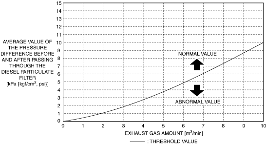
4. Display the EXP_DIF_AVE and EXH_FL using the M-MDS data logger function.
5. Drive at a constant speed for 4 s under the following conditions.
6. Verify that the values of the PIDs EXP_DIF_AVE and EXH_FL are the standard or more.
Standard
atrizt00000057
|
PID Item/Simulation Item Used In Diagnosis
PID/DATA monitor item table
|
Item |
Definition |
Unit |
Condition/Specification |
|---|---|---|---|
|
EXH_FL
|
Exhaust gas amount
|
m3/min
|
• Displays exhaust gas amount
|
|
EXHP_DIF_AVE
|
Average value of the pressure difference before and after passing through the diesel particulate filter
|
KPa {MPa}, mBar {Bar}, psi, in H20
|
• Display average value of the pressure difference before and after passing through the diesel particulate filter
|
|
PM_GEN
|
PM generation amount
|
—(g/l, lb/ft3)
|
• Displays the PM generation amount
|
Diagnostic Procedure
|
STEP |
INSPECTION |
ACTION |
|
|---|---|---|---|
|
1
|
RECORD VEHICLE STATUS AT TIME OF DTC DETECTION TO UTILIZE WITH REPEATABILITY VERIFICATION
• Record the FREEZE FRAME DATA/snapshot data on the repair order.
|
—
|
Go to the next step.
|
|
2
|
VERIFY RELATED SERVICE INFORMATION AVAILABILITY
• Verify related Service Information availability.
• Is any related Service Information available?
|
Yes
|
Perform repair or diagnosis according to the available Service Information.
• If the vehicle is not repaired, go to the next step.
|
|
No
|
Go to the next step.
|
||
|
3
|
VERIFY RELATED PENDING CODE AND/OR DTC
• Switch the ignition off, then ON (engine off).
• Perform the Pending Trouble Code Access Procedure and DTC Reading Procedure.
• Are any other PENDING CODEs and/or DTCs present?
|
Yes
|
Go to the applicable PENDING CODE or DTC inspection.
|
|
No
|
Go to the next step.
|
||
|
4
|
INSPECT EXHAUST GAS PRESSURE SENSOR NO.2 CONNECTOR CONDITION
• Switch the ignition off.
• Disconnect the exhaust gas pressure sensor No.2 connector.
• Inspect for poor connection (such as damaged/pulled-out pins, corrosion).
• Is there any malfunction?
|
Yes
|
Repair or replace the connector and/or terminals, then go to Step 7.
|
|
No
|
Go to the next step.
|
||
|
5
|
INSPECT EXHAUST GAS PRESSURE SENSOR NO.2 RELATED PIPE
• Visually inspect the exhaust gas pressure sensor No.2 related pipe for restriction and damaged.
• Is there any malfunction?
|
Yes
|
Repair or replace the malfunctioning part according to the inspection results, then go to Step 7.
|
|
No
|
Go to the next step.
|
||
|
6
|
INSPECT PCM CONNECTOR CONDITION
• Disconnect the PCM connector.
• Inspect for poor connection (such as damaged/pulled-out pins, corrosion).
• Is there any malfunction?
|
Yes
|
Repair or replace the connector and/or terminals, then go to the next step.
|
|
No
|
Go to the next step.
|
||
|
7
|
PURPOSE: VERIFICATION OF VEHICLE REPAIR COMPLETION
• Reconnect all disconnected connectors and hoses.
• Clear the DTC from the PCM memory using the M-MDS.
• Verify that repairs have been completed.
• Are the PIDs EXP_DIF_AVE, EXH_FL, and PM_GEN the standard or more?
|
Yes
|
Go to the next step.
|
|
No
|
Implement the repair completion verification procedure again.
• If a malfunction occurs, perform the inspection from Step 1.
|
||
|
8
|
VERIFY AFTER REPAIR PROCEDURE
• Perform the “AFTER REPAIR PROCEDURE”.
• Are any DTCs present?
|
Yes
|
Go to the applicable DTC inspection.
|
|
No
|
DTC troubleshooting completed.
|
||
Fuel injector (6 pin type)
|
DTC P2456:00 |
Exhaust gas pressure sensor No.2: Characteristic malfunction |
|---|---|
|
DETECTION CONDITION
|
• When the following conditions are met, the PCM detects a difference of less than 0.1 kPa {0.001 kgf/cm2, 0.01 psi} for a consecutive 8 times between the value detected by exhaust pressure sensor No.2 when the exhaust amount is 2.0 m3/min or more and the value detected by exhaust pressure sensor No.2 when the exhaust amount is less than 0.85 m3/min.
Diagnostic support note
• This is a continuous monitor (CCM).
• The check engine light illuminates if the PCM detects the above malfunction condition during the first drive cycle.
• FREEZE FRAME DATA/Snapshot data is available.
• DTC is stored in the PCM memory.
|
|
FAIL-SAFE FUNCTION
|
• Limits engine torque.
• Inhibits the automatic diesel particulate filter regeneration control.
• Inhibits the manual diesel particulate filter regeneration control.
• Inhibits the EGR control.
|
|
POSSIBLE CAUSE
|
• Exhaust gas pressure sensor No.2 connector or terminal malfunction
• Pipe clogging or damage between exhaust sensor No.2 and catalytic converter
• PCM connector or terminal malfunction
• Exhaust gas pressure sensor No.2 malfunction
• PCM malfunction
|
|
SYSTEM WIRING DIAGRAM
|
Not applicable
|
Diagnostic Procedure
|
Step |
Inspection |
Results |
Action |
|---|---|---|---|
|
1
|
RECORD VEHICLE STATUS WHEN DTC WAS DETECTED TO UTILIZE WITH REPEATABILITY VERIFICATION
• Record the freeze frame data/snap shot data.
|
—
|
Go to the next step.
|
|
2
|
INSPECT EXHAUST GAS PRESSURE SENSOR NO.2 CONNECTOR CONDITION
• Switch the ignition OFF.
• Disconnect the exhaust gas pressure sensor No.2 connector.
• Inspect the connector engagement and connection condition, and inspect the terminals for damage, deformation, corrosion, or disconnection.
• Is the connector normal?
|
Yes
|
Go to the next step.
|
|
No
|
Repair or replace the connector, then go to Step 6.
|
||
|
3
|
INSPECT EXHAUST GAS PRESSURE SENSOR NO.2-RELATED PIPING
• Visually inspect the exhaust gas pressure No.2-related piping for clogging, damage, or less.
• Is the exhaust gas pressure sensor No.2-related piping normal?
|
Yes
|
Go to the next step.
|
|
No
|
Repair or replace the malfunctioning location, then go to the next step.
|
||
|
4
|
INSPECT PCM CONNECTOR CONDITION
• Switch the ignition OFF.
• Disconnect the PCM connector.
• Inspect the connector engagement and connection condition, and inspect the terminals for damage, deformation, corrosion, or disconnection.
• Is the connector normal?
|
Yes
|
Go to the next step.
|
|
No
|
Repair or replace the connector, then go to Step 6.
|
||
|
5
|
INSPECT EXHAUST GAS PRESSURE SENSOR NO.2
• Reconnect all disconnected connectors and hoses.
• Inspect exhaust gas pressure sensor No.2.
• Is exhaust gas pressure sensor No.2 normal?
|
Yes
|
Go to the next step.
|
|
No
|
Replace exhaust gas pressure sensor No.2, then go to the next step.
|
||
|
6
|
VERIFY THAT REPAIRS HAVE BEEN COMPLETED
• Reconnect all the disconnected connectors.
• Refer to the [MEMORY CLEARING PROCEDURE] and clear the DTC.
• Perform the following operation:
• Display the DTCs using the M-MDS.
• Has DTC P2456:00 been recorded?
|
Yes
|
Repeat the inspection from Step 1.
• If the malfunction recurs, replace the PCM, then go to the next step.
|
|
No
|
Go to the next step.
|
||
|
7
|
VERIFY OTHER DTCs
• Has any other DTC or pending code been stored?
|
Yes
|
Repair the malfunctioning location according to the applicable DTC troubleshooting.
|
|
No
|
DTC troubleshooting completed.
|