|
1
|
VERIFY FREEZE FRAME DATA/SNAPSHOT DATA HAS BEEN RECORDED
• Has the FREEZE FRAME DATA/snapshot data been recorded?
|
Yes
|
Go to the next step.
|
|
No
|
Record the FREEZE FRAME DATA/snapshot data on the repair order, then go to the next step.
|
|
2
|
VERIFY RELATED SERVICE INFORMATION AVAILABILITY
• Verify related Service Information availability.
• Is any related Service Information available?
|
Yes
|
Perform repair or diagnosis according to the available Service Information.
• If the vehicle is not repaired, go to the next step.
|
|
No
|
Go to the next step.
|
|
3
|
VERIFY RELATED PENDING CODE AND/OR DTC
• Switch the ignition off, then ON (engine off).
• Perform the Pending Trouble Code Access Procedure and DTC Reading Procedure.
• Is the PENDING CODE/DTC P0703:00 also present?
|
Yes
|
Go to the applicable PENDING CODE or DTC inspection.
|
|
No
|
Go to the next step.
|
|
4
|
INSPECT BRAKE SWITCH CONNECTOR CONDITION
• Switch the ignition off.
• Disconnect the brake switch connector.
• Inspect for poor connection (such as damaged/pulled-out pins, corrosion).
• Is there any malfunction?
|
Yes
|
Repair or replace the connector and/or terminals, then go to Step 12.
|
|
No
|
Go to the next step.
|
|
5
|
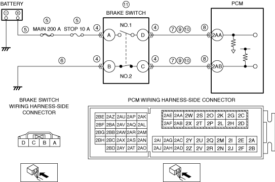
INSPECT BRAKE SWITCH NO.1 POWER SUPPLY CIRCUIT FOR SHORT TO GROUND OR OPEN CIRCUIT
• Verify that the brake switch connector is disconnected.
• Measure the voltage at the brake switch terminal A (wiring harness-side).
• Is the voltage B+?
|
Yes
|
Go to the next step.
|
|
No
|
Inspect the MAIN 200 A fuse and STOP 10 A fuse.
• If the fuse is blown:
-
― Refer to the wiring diagram and verify whether or not there is a common connector between MAIN 200 A fuse and brake switch terminal A.
If there is a common connector:
-
• Determine the malfunctioning part by inspecting the common connector and the terminal for corrosion, damage, or pin disconnection, and the common wiring harness for a short to ground.
• Repair or replace the malfunctioning part.
If there is no common connector:
-
• Repair or replace the wiring harness which has a short to ground.
• Replace the fuse.
• If the fuse is damaged:
-
― Replace the fuse.
• If all fuses are normal:
-
― Refer to the wiring diagram and verify whether or not there is a common connector between battery positive terminal and brake switch terminal A.
If there is a common connector:
-
• Determine the malfunctioning part by inspecting the common connector and the terminal for corrosion, damage, or pin disconnection, and the common wiring harness for an open circuit.
• Repair or replace the malfunctioning part.
If there is no common connector:
-
• Repair or replace the wiring harness which has an open circuit.
Go to Step 12.
|
|
6
|
INSPECT BRAKE SWITCH NO.2 GROUND CIRCUIT FOR OPEN CIRCUIT
• Verify that the brake switch connector is disconnected.
• Inspect for continuity between brake switch terminal B (wiring harness-side) and body ground.
• Is there continuity?
|
Yes
|
Go to the next step.
|
|
No
|
Refer to the wiring diagram and verify whether or not there is a common connector between brake switch terminal B and body ground.
If there is a common connector:
• Determine the malfunctioning part by inspecting the common connector and the terminal for corrosion, damage, or pin disconnection, and the common wiring harness for an open circuit.
• Repair or replace the malfunctioning part.
If there is no common connector:
• Inspect for the following:
-
― Open circuit between brake switch and body ground
― Loose or lifting ground point
-
• Repair or replace the malfunctioning part.
Go to Step 12.
|
|
7
|
INSPECT BRAKE SWITCH SIGNAL CIRCUIT FOR SHORT TO GROUND
• Verify that the brake switch connector is disconnected.
• Inspect for continuity between the following terminals (wiring harness-side) and body ground:
-
― Brake switch terminal D
― Brake switch terminal C
• Is there continuity?
|
Yes
|
If the short to ground circuit could be detected in the wiring harness:
• Refer to the wiring diagram and verify whether or not there is a common connector between the following terminals:
-
― Brake switch terminal D—PCM terminal 2AA
― Brake switch terminal C—PCM terminal 2AB
If there is a common connector:
-
― Determine the malfunctioning part by inspecting the common connector and the terminal for corrosion, damage, or pin disconnection, and the common wiring harness for a short to ground.
― Repair or replace the malfunctioning part.
If there is no common connector:
-
― Repair or replace the wiring harness which has a short to ground.
If the short to ground circuit could not be detected in the wiring harness:
• Replace the PCM (short to ground in the PCM internal circuit).
Go to Step 12.
|
|
No
|
Go to the next step.
|
|
8
|
INSPECT PCM CONNECTOR CONDITION
• Disconnect the PCM connector.
• Inspect for poor connection (such as damaged/pulled-out pins, corrosion).
• Is there any malfunction?
|
Yes
|
Repair or replace the connector and/or terminals, then go to Step 12.
|
|
No
|
Go to the next step.
|
|
9
|
INSPECT BRAKE SWITCH SIGNAL CIRCUIT FOR SHORT TO POWER SUPPLY
• Verify that the brake switch and PCM connectors are disconnected.
• Switch the ignition ON (engine off).
• Measure the voltage at the following terminals (wiring harness-side):
-
― Brake switch terminal D
― Brake switch terminal C
• Is the voltage 0 V?
|
Yes
|
Go to the next step.
|
|
No
|
Refer to the wiring diagram and verify whether or not there is a common connector between the following terminals:
• Brake switch terminal D—PCM terminal 2AA
• Brake switch terminal C—PCM terminal 2AB
If there is a common connector:
• Determine the malfunctioning part by inspecting the common connector and the terminal for corrosion, damage, or pin disconnection, and the common wiring harness for a short to power supply.
• Repair or replace the malfunctioning part.
If there is no common connector:
• Repair or replace the wiring harness which has a short to power supply.
Go to Step 12.
|
|
10
|
INSPECT BRAKE SWITCH SIGNAL CIRCUIT FOR OPEN CIRCUIT
• Verify that the brake switch and PCM connectors are disconnected.
• Switch the ignition off.
• Inspect for continuity between the following terminals (wiring harness-side):
-
― Brake switch terminal D—PCM terminal 2AA
― Brake switch terminal C—PCM terminal 2AB
• Is there continuity?
|
Yes
|
Go to the next step.
|
|
No
|
Refer to the wiring diagram and verify whether or not there is a common connector between the following terminals:
• Brake switch terminal D—PCM terminal 2AA
• Brake switch terminal C—PCM terminal 2AB
If there is a common connector:
• Determine the malfunctioning part by inspecting the common connector and the terminal for corrosion, damage, or pin disconnection, and the common wiring harness for an open circuit.
• Repair or replace the malfunctioning part.
If there is no common connector:
• Repair or replace the wiring harness which has an open circuit.
Go to Step 12.
|
|
11
|
INSPECT BRAKE SWITCH
• Inspect the brake switch.
• Is there any malfunction?
|
Yes
|
Replace the brake switch, then go to the next step.
|
|
No
|
Go to the next step.
|
|
12
|
VERIFY DTC TROUBLESHOOTING COMPLETED
• Always reconnect all disconnected connectors.
• Clear the DTC from the PCM memory using the M-MDS.
• Start the engine and idle it.
• Perform the following operations above 5 times.
-
1. Depress the brake pedal for 5 s.
2. Release the brake pedal for 5 s.
• Perform the Pending Trouble Code Access Procedure.
• Is the PENDING CODE for this DTC present?
|
Yes
|
Repeat the inspection from Step 1.
• If the malfunction recurs, replace the PCM.
Go to the next step.
|
|
No
|
Go to the next step.
|
|
13
|
VERIFY AFTER REPAIR PROCEDURE
• Perform the “AFTER REPAIR PROCEDURE”.
• Are any DTCs present?
|
Yes
|
Go to the applicable DTC inspection.
|
|
No
|
DTC troubleshooting completed.
|