|
1
|
IDENTIFY TRIGGER DTC FOR FREEZE FRAME DATA
• Perform the Freeze Frame PID Data Access Procedure.
• Is the DTC P2A00:00 on FREEZE FRAME DATA?
|
Yes
|
Go to the next step.
|
|
No
|
Go to the troubleshooting procedure for DTC on FREEZE FRAME DATA.
|
|
2
|
VERIFY FREEZE FRAME DATA/SNAPSHOT DATA AND DIAGNOSTIC MONITORING TEST RESULTS HAVE BEEN RECORDED
• Have the FREEZE FRAME DATA/snapshot data and DIAGNOSTIC MONITORING TEST RESULTS (A/F sensor related) been recorded?
|
Yes
|
Go to the next step.
|
|
No
|
Record the FREEZE FRAME DATA/snapshot data and DIAGNOSTIC MONITORING TEST RESULTS on the repair order, then go to the next step.
|
|
3
|
VERIFY RELATED SERVICE INFORMATION AVAILABILITY
• Verify related Service Information availability.
• Is any related Service Information available?
|
Yes
|
Perform repair or diagnosis according to the available Service Information.
• If the vehicle is not repaired, go to the next step.
|
|
No
|
Go to the next step.
|
|
4
|
VERIFY RELATED PENDING CODE AND/OR DTC
• Switch the ignition off, then ON (engine off).
• Perform the Pending Trouble Code Access Procedure and DTC Reading Procedure.
• Are any other PENDING CODEs and/or DTCs present?
|
Yes
|
Go to the applicable PENDING CODE or DTC inspection.
|
|
No
|
Go to the next step.
|
|
5
|
INSPECT A/F SENSOR HEATER
• Inspect the A/F sensor heater.
• Is there any malfunction?
|
Yes
|
Replace the A/F sensor, then go to Step 16.
|
|
No
|
Go to the next step.
|
|
6
|
INSPECT A/F SENSOR
• Inspect the A/F sensor.
• Is there any malfunction?
|
Yes
|
Go to the next step.
|
|
No
|
Go to Step 9.
|
|
7
|
INSPECT INSTALLATION OF A/F SENSOR
• Inspect installation of A/F sensor.
• Is the A/F sensor installed securely?
|
Yes
|
Go to the next step.
|
|
No
|
Retighten the A/F sensor, then go to Step 16.
|
|
8
|
INSPECT EXHAUST SYSTEM FOR LEAKAGE
• Visually inspect for exhaust gas leakage in the exhaust system.
• Is there any leakage?
|
Yes
|
Repair or replace the malfunctioning part according to the inspection results, then go to Step 16.
|
|
No
|
Replace the A/F sensor, then go to Step 16.
|
|
9
|
INSPECT A/F SENSOR CONNECTOR CONDITION
• Switch the ignition off.
• Disconnect the A/F sensor connector.
• Inspect for poor connection (such as damaged/pulled-out pins, corrosion).
• Is there any malfunction?
|
Yes
|
Repair or replace the connector and/or terminals, then go to Step 16.
|
|
No
|
Go to the next step.
|
|
10
|
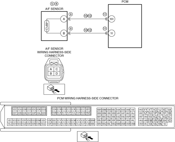
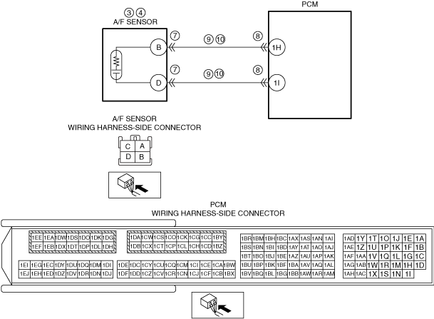
INSPECT A/F SENSOR CIRCUIT FOR SHORT TO GROUND
• Verify that the A/F sensor connector is disconnected.
• Inspect for continuity between the following terminals (wiring harness-side) and body ground:
-
― A/F sensor terminal A
― A/F sensor terminal B
• Is there continuity?
|
Yes
|
If the short to ground circuit could be detected in the wiring harness:
• Refer to the wiring diagram and verify whether or not there is a common connector between the following terminals:
-
― A/F sensor terminal A—PCM terminal 1H
― A/F sensor terminal B—PCM terminal 1I
If there is a common connector:
-
― Determine the malfunctioning part by inspecting the common connector and the terminal for corrosion, damage, or pin disconnection, and the common wiring harness for a short to ground.
― Repair or replace the malfunctioning part.
If there is no common connector:
-
― Repair or replace the wiring harness which has a short to ground.
If the short to ground circuit could not be detected in the wiring harness:
• Replace the PCM (short to ground in the PCM internal circuit).
Go to Step 16.
|
|
No
|
Go to the next step.
|
|
11
|
INSPECT PCM CONNECTOR CONDITION
• Disconnect the PCM connector.
• Inspect for poor connection (such as damaged/pulled-out pins, corrosion).
• Is there any malfunction?
|
Yes
|
Repair or replace the connector and/or terminals, then go to Step 16.
|
|
No
|
Go to the next step.
|
|
12
|
INSPECT A/F SENSOR CIRCUIT FOR OPEN CIRCUIT
• Verify that the A/F sensor and PCM connectors are disconnected.
• Inspect for continuity between the following terminals (wiring harness-side):
-
― A/F sensor terminal A—PCM terminal 1H
― A/F sensor terminal B—PCM terminal 1I
• Is there continuity?
|
Yes
|
Go to the next step.
|
|
No
|
Refer to the wiring diagram and verify whether or not there is a common connector between the following terminals:
• A/F sensor terminal A—PCM terminal 1H
• A/F sensor terminal B—PCM terminal 1I
If there is a common connector:
• Determine the malfunctioning part by inspecting the common connector and the terminal for corrosion, damage, or pin disconnection, and the common wiring harness for an open circuit.
• Repair or replace the malfunctioning part.
If there is no common connector:
• Repair or replace the wiring harness which has an open circuit.
Go to Step 16.
|
|
13
|
INSPECT ENGINE COMPRESSION
• Inspect the engine compression.
• Are compression pressures within specification?
|
Yes
|
Go to the next step.
|
|
No
|
Repair or replace the malfunctioning part according to the inspection results, then go to Step 16.
|
|
14
|
INSPECT SEALING OF ENGINE COOLANT PASSAGE
• Perform the “ENGINE COOLANT LEAKAGE INSPECTION”.
• Does the radiator cap tester needle drop even though there is no engine coolant leakage from the radiator or the hoses?
|
Yes
|
Engine coolant leakage from the engine (between the combustion chamber and the engine coolant passage) may have occurred.
• Verify the conditions of the gasket and the cylinder head.
-
― If there is any malfunction:
-
• Repair or replace the malfunctioning part according to the inspection results, then go to Step 16.
|
|
No
|
Go to the next step.
|
|
15
|
INSPECT FOR MALFUNCTION DUE TO INTERNAL ENGINE WEAR, DAMAGE
• Inspect for the following engine internal parts:
-
― Cylinder
― Piston ring
― Intake valve
― Exhaust valve
― Such as cylinder head gasket
• Are all items normal?
|
Yes
|
Engine internal parts are normal.
• Go to the next step.
|
|
No
|
Repair or replace the malfunctioning part according to the inspection results, then go to the next step.
|
|
16
|
VERIFY DTC TROUBLESHOOTING COMPLETED
• Always reconnect all disconnected connectors.
• Clear the DTC from the PCM memory using the M-MDS.
• Start the engine and idle it.
• Wait until the ECT PID value is above 80 °C {176 °F}.
• Wait for 1 min (idle).
• Perform the DTC Reading Procedure.
• Is the same DTC present?
|
Yes
|
Repeat the inspection from Step 1.
• If the malfunction recurs, replace the PCM.
Go to the next step.
|
|
No
|
Go to the next step.
|
|
17
|
VERIFY AFTER REPAIR PROCEDURE
• Perform the “AFTER REPAIR PROCEDURE”.
• Are any DTCs present?
|
Yes
|
Go to the applicable DTC inspection.
|
|
No
|
DTC troubleshooting completed.
|