49 L018 001
O2 sensor wrench

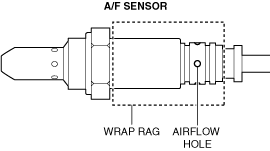
AIR FUEL RATIO (A/F) SENSOR REMOVAL/INSTALLATION [SKYACTIV-D 2.2]
id0140z7899700
Special Service Tool (SST)
|
49 L018 001
O2 sensor wrench
|
|
ac5wzw00007835
|
Operation After Replacing A/F Sensor
1. If the A/F sensor is replaced, perform the following procedure.
Fuel injector (2pin type)
|
Step |
Action |
Page |
|---|---|---|
|
1
|
Perform the A/F sensor data reset procedure.
|
|
|
2
|
Switch the ignition off.
|
—
|
|
3
|
Wait for 20 s.
|
—
|
|
4
|
Switch the ignition ON (engine off).
|
—
|
|
5
|
Perform the KOEO self test procedure.
|
|
|
6
|
Start the engine.
|
—
|
|
7
|
Verify that the check engine light does not illuminate.
|
—
|
|
8
|
Perform the KOER self test procedure.
|
|
|
9
|
Perform the compulsory diesel particulate filter regeneration procedure.
|
|
|
10
|
Perform the following procedure.
1. Vehicle is traveling at a speed of 50 km/h {31 mph} or more.
2. Release the accelerator pedal at a vehicle speed of 50 km/h {31 mph} or more and maintain this condition for 6 s.
|
—
|
|
11
|
Verify that the PID “O2S11_CAL” value is other than 0.
|
Fuel injector (6pin type)
|
Step |
Action |
Page |
|---|---|---|
|
1
|
Perform the A/F sensor data reset procedure.
|
|
|
2
|
Switch the ignition off.
|
—
|
|
3
|
Wait for 30 s.
|
—
|
|
4
|
Switch the ignition ON (engine off).
|
—
|
|
5
|
Perform the KOEO self test procedure.
|
|
|
6
|
Start the engine.
|
—
|
|
7
|
Verify that the check engine light does not illuminate.
|
—
|
|
8
|
Perform the KOER self test procedure.
|
|
|
9
|
Perform the following procedure.
1. Vehicle is traveling at a speed of 50 km/h {31 mph} or more.
2. Remove your foot from the accelerator pedal at a vehicle speed of 50 km/h {31 mph} or more.
|
—
|
|
10
|
Verify that the PID “O2S11_CAL” value is other than 0.
|
|
|
11
|
Perform the compulsory diesel particulate filter regeneration procedure.
|
A/F Sensor Removal/Installation (Fuel injector (2pin type))
ac5wzw00004500
|
1. Disconnect the negative battery terminal. (See NEGATIVE BATTERY TERMINAL DISCONNECTION/CONNECTION.)
2. Lift up the vehicle.
3. Remove the front under cover No.2. (2WD)(See FRONT UNDER COVER No.2 REMOVAL/INSTALLATION.)
4. Remove the front splash shield (RH). (See SPLASH SHIELD REMOVAL/INSTALLATION.)
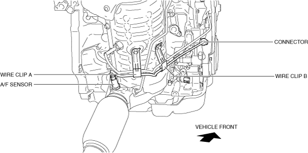
5. Disconnect the A/F sensor connector.
6. Remove the plate (exhaust system). (See EXHAUST SYSTEM REMOVAL/INSTALLATION [SKYACTIV-D 2.2].)
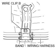
7. Remove the wiring harness from the wire clip A and B. (See Assembly of Wiring Harness to Wire Clip Note.)
ac5wzw00004501
|
8. Loosen the nuts (center bearing support) of the propeller shaft. (4WD) (See PROPELLER SHAFT REMOVAL/INSTALLATION.)
9. Disconnect the propeller shaft on the front side and set the propeller shaft onto the front crossmember. (4WD) (See PROPELLER SHAFT REMOVAL/INSTALLATION.)
10. Remove the A/F sensor using the SST.
ac5wzw00004502
|
11. Install in the reverse order of removal.
12. Perform operation after replacing A/F sensor. (See Operation After Replacing A/F Sensor.)
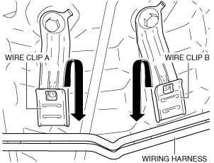
Assembly of Wiring Harness to Wire Clip Note
ac5wzw00004503
|
ac5wzw00004504
|
A/F Sensor Removal/Installation (Fuel Injector (6Pin Type))
ac5wzw00012112
|
1. Disconnect the negative battery terminal. (See NEGATIVE BATTERY TERMINAL DISCONNECTION/CONNECTION.)
2. Turn the steering wheel completely to the right.
3. Lift up the vehicle.
4. Remove the front splash shield (RH). (See SPLASH SHIELD REMOVAL/INSTALLATION.)
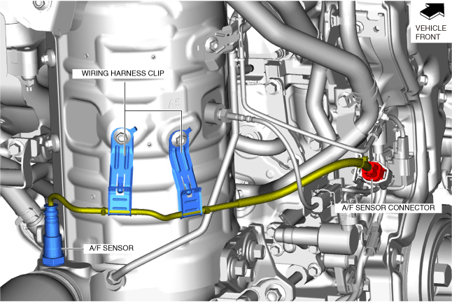
5. Disconnect the A/F sensor connector.
6. Remove the plate (exhaust system). (See EXHAUST SYSTEM REMOVAL/INSTALLATION [SKYACTIV-D 2.2].)
7. Remove the wiring harness from the wire clip. (See Assembly of Wiring Harness to Wire Clip Note.)
ac5wzw00012113
|
8. Loosen the nuts (center bearing support) of the propeller shaft. (4WD) (See PROPELLER SHAFT REMOVAL/INSTALLATION.)
9. Disconnect the propeller shaft on the front side and set the propeller shaft onto the front crossmember. (4WD) (See PROPELLER SHAFT REMOVAL/INSTALLATION.)
10. Remove the A/F sensor using the SST.
ac5wzw00012114
|
11. Install in the reverse order of removal.
12. Perform operation after replacing A/F sensor. (See Operation After Replacing A/F Sensor.)
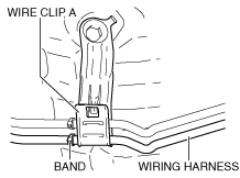
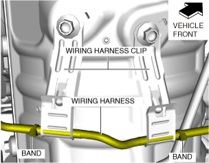
Assembly of Wiring Harness to Wire Clip Note
1. Secure the wiring harness to the wire clip so that the band on the wiring harness is positioned to the left side of the wire clip.
ac5wzw00012115
|