|
1
|
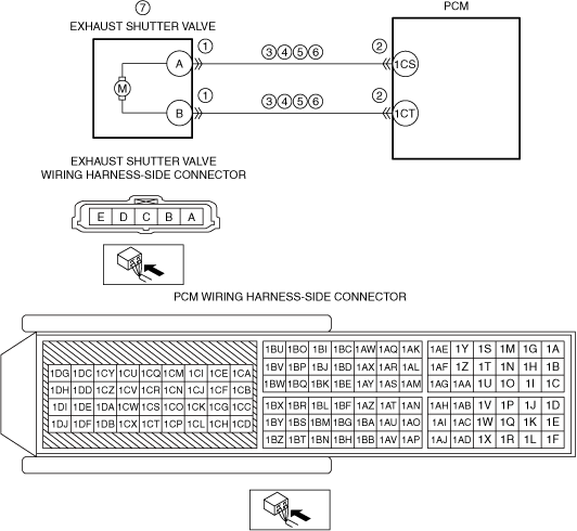
PURPOSE: INSPECT EXHAUST SHUTTER VALVE CONNECTOR CONDITION
• Switch the ignition off.
• Disconnect the exhaust shutter valve connector.
• Inspect for poor connection (such as damaged/pulled-out pins, corrosion).
• Is there any malfunction?
|
Yes
|
Repair or replace the connector and/or terminals, then go to Step 8.
|
|
No
|
Go to the next step.
|
|
2
|
PURPOSE: INSPECT PCM CONNECTOR CONDITION
• Disconnect the PCM connector.
• Inspect for poor connection (such as damaged/pulled-out pins, corrosion).
• Is there any malfunction?
|
Yes
|
Repair or replace the connector and/or terminals, then go to Step 8.
|
|
No
|
Go to the next step.
|
|
3
|
PURPOSE: INSPECT EXHAUST SHUTTER VALVE CIRCUIT FOR SHORT TO GROUND
• Verify that the exhaust shutter valve and PCM connectors are disconnected.
• Inspect for continuity between the following terminals (wiring harness-side) and body ground:
-
― Exhaust shutter valve terminal A
― Exhaust shutter valve terminal B
• Is there continuity?
|
Yes
|
Refer to the wiring diagram and verify whether or not there is a common connector between the following terminals:
• Exhaust shutter valve terminal A—PCM terminal 1CS
• Exhaust shutter valve terminal B—PCM terminal 1CT
If there is a common connector:
• Determine the malfunctioning part by inspecting the common connector and the terminal for corrosion, damage, or pin disconnection, and the common wiring harness for a short to ground.
• Repair or replace the malfunctioning part.
If there is no common connector:
• Repair or replace the wiring harness which has a short to ground.
Go to Step 8.
|
|
No
|
Go to the next step.
|
|
4
|
PURPOSE: INSPECT EXHAUST SHUTTER VALVE CIRCUITS FOR SHORT CIRCUIT
• Verify that the exhaust shutter valve and PCM connectors are disconnected.
• Inspect for continuity between exhaust shutter valve terminals A and B (wiring harness-side).
• Is there continuity?
|
Yes
|
Refer to the wiring diagram and verify whether or not there is a common connector between the following terminals:
• Exhaust shutter valve terminal A—PCM terminal 1CS
• Exhaust shutter valve terminal B—PCM terminal 1CT
If there is a common connector:
• Determine the malfunctioning part by inspecting the common connector and the terminal for corrosion, damage, or pin disconnection, and the common wiring harness for a short to each other.
• Repair or replace the malfunctioning part.
If there is no common connector:
• Repair or replace the wiring harness which has a short to each other.
Go to Step 8.
|
|
No
|
Go to the next step.
|
|
5
|
PURPOSE: INSPECT EXHAUST SHUTTER VALVE CIRCUIT FOR SHORT TO POWER SUPPLY
• Verify that the exhaust shutter valve and PCM connectors are disconnected.
• Switch the ignition ON (engine off).
-
Note
-
• Another DTC may be stored by the PCM detecting an open circuit.
• Measure the voltage at the following terminals (wiring harness-side):
-
― Exhaust shutter valve terminal A
― Exhaust shutter valve terminal B
• Is the voltage 0 V?
|
Yes
|
Go to the next step.
|
|
No
|
Refer to the wiring diagram and verify whether or not there is a common connector between the following terminals:
• Exhaust shutter valve terminal A—PCM terminal 1CS
• Exhaust shutter valve terminal B—PCM terminal 1CT
If there is a common connector:
• Determine the malfunctioning part by inspecting the common connector and the terminal for corrosion, damage, or pin disconnection, and the common wiring harness for a short to power supply.
• Repair or replace the malfunctioning part.
If there is no common connector:
• Repair or replace the wiring harness which has a short to power supply.
Go to Step 8.
|
|
6
|
PURPOSE: INSPECT EXHAUST SHUTTER VALVE CIRCUIT FOR OPEN CIRCUIT
• Verify that the exhaust shutter valve and PCM connectors are disconnected.
• Switch the ignition off.
• Inspect for continuity between the following terminals (wiring harness-side):
-
― Exhaust shutter valve terminal A—PCM terminal 1CS
― Exhaust shutter valve terminal B—PCM terminal 1CT
• Is there continuity?
|
Yes
|
Go to the next step.
|
|
No
|
Refer to the wiring diagram and verify whether or not there is a common connector between the following terminals:
• Exhaust shutter valve terminal A—PCM terminal 1CS
• Exhaust shutter valve terminal B—PCM terminal 1CT
If there is a common connector:
• Determine the malfunctioning part by inspecting the common connector and the terminal for corrosion, damage, or pin disconnection, and the common wiring harness for an open circuit.
• Repair or replace the malfunctioning part.
If there is no common connector:
• Repair or replace the wiring harness which has an open circuit.
Go to Step 8.
|
|
7
|
PURPOSE: INSPECT EXHAUST SHUTTER VALVE
• Reconnect all disconnected connectors.
• Inspect the exhaust shutter valve.
• Is there any malfunction?
|
Yes
|
Replace the TWC, then go to the next step.
|
|
No
|
Go to the next step.
|
|
8
|
PURPOSE: VERIFY DTC TROUBLESHOOTING COMPLETED
• Always reconnect all disconnected connectors.
• Clear the DTC from the PCM memory using the M-MDS.
• Implement the repeatability verification procedure.
• Perform the Pending Trouble Code Access Procedure.
• Is the PENDING CODE for this DTC present?
|
Yes
|
Repeat the inspection from Step 1.
• If the malfunction recurs, replace the PCM.
Go to the next step.
|
|
No
|
Go to the next step.
|
|
9
|
PURPOSE: VERIFY IF THERE IS ANY OTHER MALFUNCTION
• Is any other DTC or pending code stored?
|
Yes
|
Go to the applicable DTC inspection.
|
|
No
|
DTC troubleshooting completed.
|