|
ac5uuw00006922
ENGINE MOUNT DISASSEMBLY/ASSEMBLY [WITHOUT CYLINDER DEACTIVATION (SKYACTIV-G 2.0, SKYACTIV-G 2.5)]
id0110m1806900
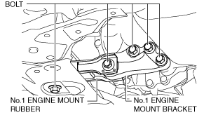
No.1 Engine Mount (2WD)
1. Remove the front under cover No.2. (See FRONT UNDER COVER No.2 REMOVAL/INSTALLATION.)
2. Remove in the order indicated in the table.
3. Install in the reverse order of removal.
ac5uuw00006922
|
|
1
|
No.1 engine mount bracket
|
|
2
|
No.1 engine mount rubber
|
No.1 engine mount installation note (2WD)
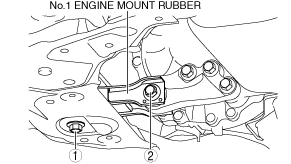
1. Install the No.1 engine mount rubber and bracket, and temporarily tighten the bolts shown in the figure.
ac5uuw00006923
|
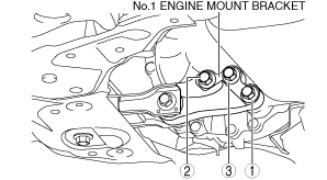
2. Tighten the No.1 engine mount bracket installation bolts in the order shown in the figure.
ac5uuw00006924
|
3. Tighten the No.1 engine mount rubber installation bolts in the order shown in the figure.
ac5uuw00006925
|
Tightening torque
|
Installation position |
Tightening torque |
|---|---|
|
1
|
141—172 N·m {15—17 kgf·m, 104—126 ft·lbf}
|
|
2
|
130—164 N·m {14—16 kgf·m, 96—120 ft·lbf}
|
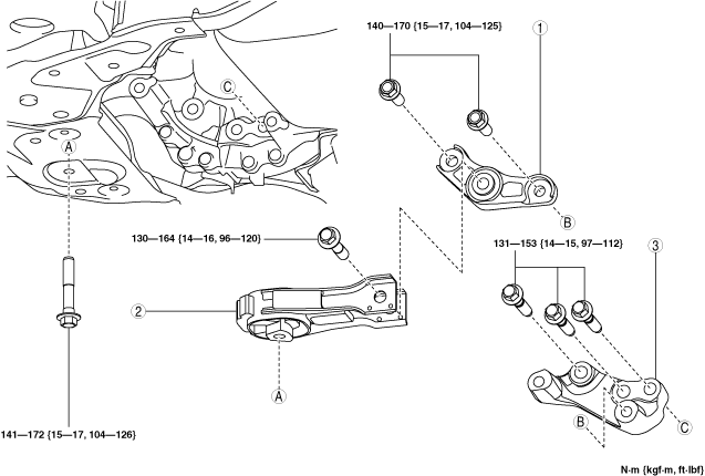
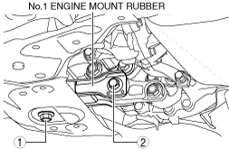
No.1 Engine Mount (4WD)
1. Remove the front under cover No.2. (See FRONT UNDER COVER No.2 REMOVAL/INSTALLATION.)
2. Remove in the order indicated in the table.
3. Install in the reverse order of removal.
ac5uuw00006926
|
|
1
|
No.1 engine mount bracket A
|
|
2
|
No.1 engine mount rubber
|
|
3
|
No.1 engine mount bracket B
|
No.1 engine mount removal note (4WD)
1. Loosen the No.1 engine mount rubber installation bolt (front crossmember side).
ac5uuw00006927
|
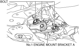
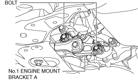
2. Remove the bolts shown in the figure and remove the No.1 engine mount bracket A.
ac5uuw00006928
|
3. Remove the No.1 engine mount rubber.
4. Remove the transfer. (See TRANSFER REMOVAL/INSTALLATION [FW6AX-EL].)
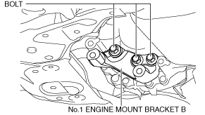
5. Remove the bolts shown in the figure and remove the No.1 engine mount bracket B.
ac5uuw00006929
|
No.1 engine mount installation note (4WD)
1. Install the No.1 engine mount bracket B and temporarily tighten the bolts shown in the figure.
ac5uuw00006929
|
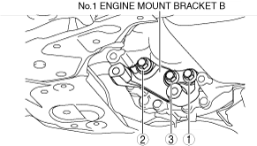
2. Tighten the No.1 engine mount bracket B installation bolts in the order shown in the figure.
ac5uuw00006930
|
3. Install the transfer. (See TRANSFER REMOVAL/INSTALLATION [FW6AX-EL].)
4. Install the No.1 engine mount bracket A and No.1 engine mount rubber, and temporarily tighten the bolts shown in the figure.
ac5uuw00006931
|
5. Tighten the No.1 engine mount bracket A installation bolts to the specified tightening torque.
ac5uuw00006932
|
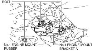
6. Tighten the No.1 engine mount rubber installation bolts in the order shown in the figure.
ac5uuw00006933
|
Tightening torque
|
Installation position |
Tightening torque |
|---|---|
|
1
|
141—172 N·m {15—17 kgf·m, 104—126 ft·lbf}
|
|
2
|
130—164 N·m {14—16 kgf·m, 96—120 ft·lbf}
|
No.3 Engine Mount
1. Remove the plug hole plate. (See PLUG HOLE PLATE REMOVAL/INSTALLATION [WITHOUT CYLINDER DEACTIVATION (SKYACTIV-G 2.0, SKYACTIV-G 2.5)].)
2. Remove in the order indicated in the table.
3. Install in the reverse order of removal.
ac5wzw00002797
|
|
1
|
No.3 engine mount
|
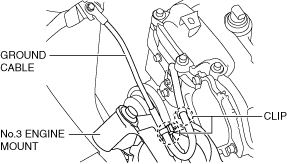
No.3 engine mount removal note
1. Remove the clips shown in the figure and set the ground cable aside.
ac5uuw00006934
|
2. Remove the front under cover No.2. (See FRONT UNDER COVER No.2 REMOVAL/INSTALLATION.)
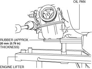
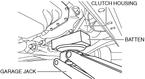
3. Before removing the No.3 engine mount, support the engine (oil pan) using a commercially available engine lifter or garage jack.
ac5uuw00006935
|
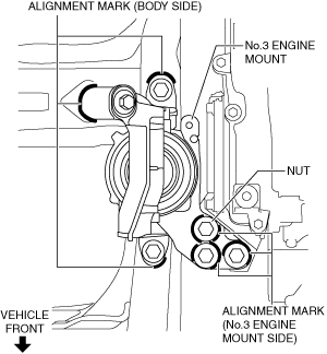
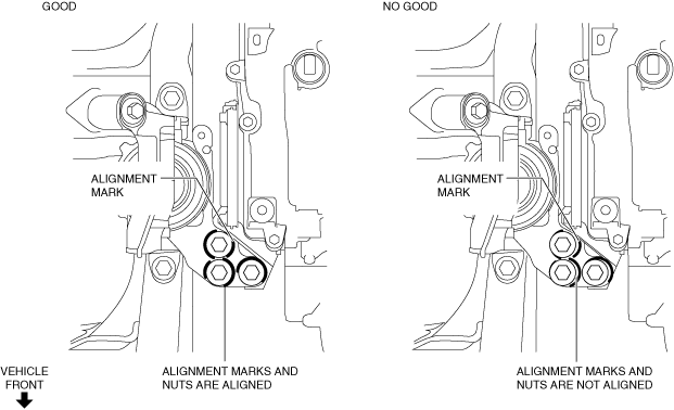
4. Place alignment marks on the locations shown in the figure so that they can be assembled to the same positions as before removal.
ac5uuw00006936
|
5. Remove the No.3 engine mount.
No.3 engine mount installation note
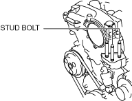
1. Tighten the engine front cover stud bolts.
ac5uuw00003260
|
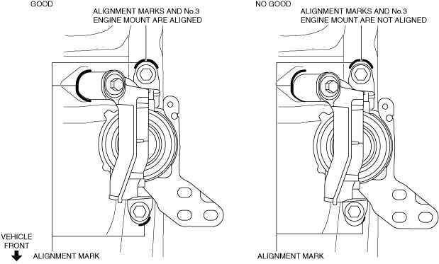
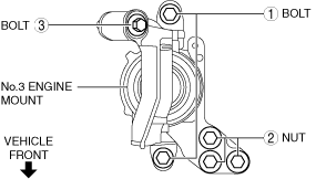
2. Temporarily tighten the No.3 engine mount installation bolts and nuts using the following procedure:
ac5uuw00006995
|
ac5uuw00006938
|
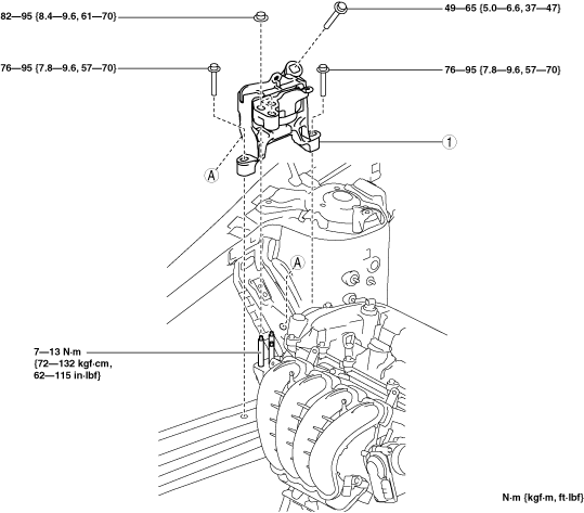
3. Tighten the No.3 engine mount installation bolts and nuts in the order shown in the figure.
ac5uuw00006939
|
Tightening torque
|
Installation position |
Tightening torque |
|---|---|
|
1
|
76—95 N·m {7.8—9.6 kgf·m, 57—70 ft·lbf}
|
|
2
|
82—95 N·m {8.4—9.6 kgf·m, 61—70 ft·lbf}
|
|
3
|
49—65 N·m {5.0—6.6 kgf·m, 37—47 ft·lbf}
|
4. Remove the engine lifter or garage jack.
5. Install the ground cable to the No.3 engine mount.
ac5uuw00006934
|
No.4 Engine Mount
1. Disconnect the negative battery terminal. (See NEGATIVE BATTERY TERMINAL DISCONNECTION/CONNECTION.)
2. Remove the air cleaner, air hose and fresh air duct as a single unit. (See INTAKE-AIR SYSTEM REMOVAL/INSTALLATION [WITHOUT CYLINDER DEACTIVATION (SKYACTIV-G 2.0, SKYACTIV-G 2.5)].)
3. Remove the PCM component. (See PCM REMOVAL/INSTALLATION [WITHOUT CYLINDER DEACTIVATION (SKYACTIV-G 2.0, SKYACTIV-G 2.5)].)
4. Remove the battery and battery tray. (See BATTERY REMOVAL/INSTALLATION [WITHOUT CYLINDER DEACTIVATION (SKYACTIV-G 2.0, SKYACTIV-G 2.5)].)
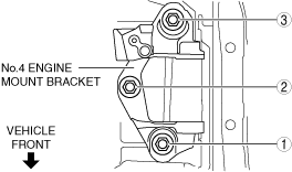
5. Remove in the order indicated in the table.
6. Install in the reverse order of removal.
ac5uuw00006940
|
|
1
|
No.4 engine mount rubber
|
|
2
|
No.4 engine mount bracket
|
No.4 engine mount rubber removal note
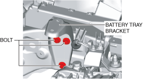
1. Loosen the battery tray bracket installation bolts.
ac5uuw00006941
|
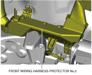
2. Set front wiring harness protector No.2 aside in the direction of the arrow shown in the figure. (See FRONT WIRING HARNESS PROTECTOR REMOVAL/INSTALLATION.)
ac5uuw00006942
|
3. Remove the front under cover No.2. (See FRONT UNDER COVER No.2 REMOVAL/INSTALLATION.)
ac5uuw00000661
|
ac5uuw00006943
|
4. Before removing the No.4 engine mount rubber, support the transaxle using a commercially available engine lifter or garage jack.
5. Remove the No.4 engine mount rubber.
No.4 engine mount bracket removal note
1. Remove the bolt shown in the figure and set the ground cable aside.
MTX
ac5uuw00006944
|
ATX
ac5uuw00006945
|
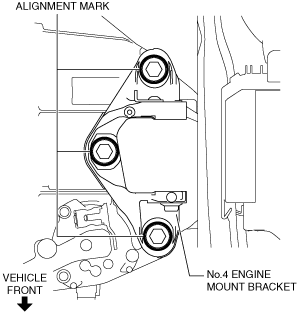
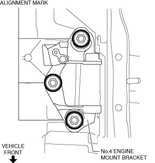
2. Place alignment marks on the locations shown in the figure so that they can be assembled to the same positions as before removal.
MTX
ac5uuw00006946
|
ATX
ac5uuw00006947
|
3. Remove the No.4 engine mount bracket.
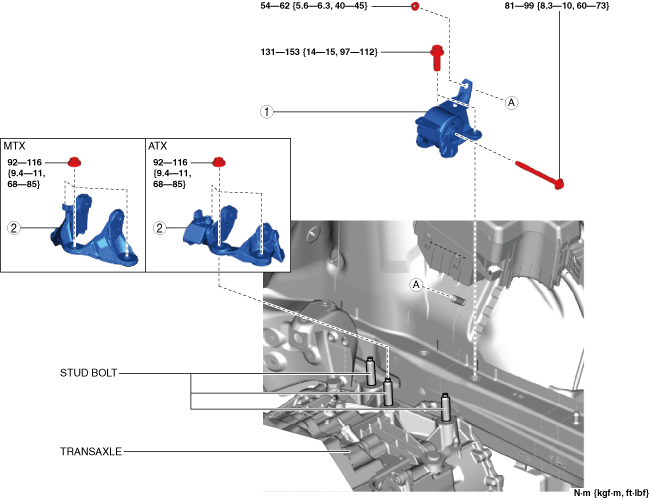
No.4 engine mount bracket installation note
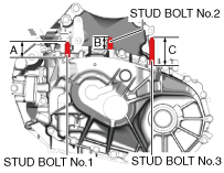
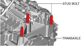
1. Measure the projection of the transaxle stud bolts. (MTX)
ac5uuw00006948
|
2. Tighten the transaxle stud bolts. (ATX)
ac5uuw00006949
|
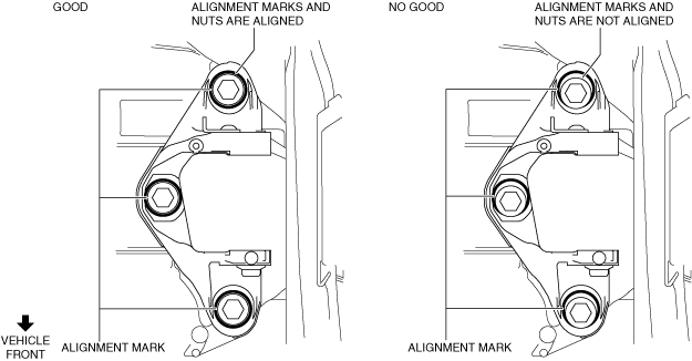
3. Align the alignment marks on the No.4 engine mount bracket and nuts, and temporarily tighten the nuts shown in the figure.
MTX
ac5uuw00006950
|
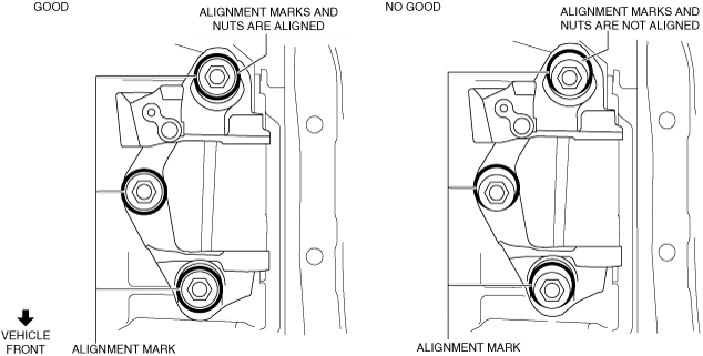
ATX
ac5uuw00006951
|
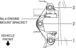
4. Tighten the No.4 engine mount bracket installation nuts in the order shown in the figure.
MTX
ac5uuw00006952
|
ATX
ac5uuw00006953
|
5. Install the ground cable to the No.4 engine mount bracket.
MTX
ac5uuw00006944
|
ATX
ac5uuw00006945
|
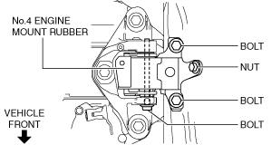
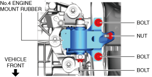
No.4 engine mount rubber installation note
1. Install the No.4 engine mount rubber and temporarily tighten the bolts and nut shown in the figure.
MTX
ac5uuw00006954
|
ATX
ac5uuw00006955
|
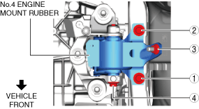
2. Tighten the No.4 engine mount rubber installation bolts and nut in the order shown in the figure.
MTX
ac5uuw00006956
|
ATX
ac5uuw00006957
|
Tightening torque
|
Installation position |
Tightening torque |
|---|---|
|
1, 2
|
131—153 N·m {14—15 kgf·m, 97—112 ft·lbf}
|
|
3
|
54—62 N·m {5.6—6.3 kgf·m, 40—45 ft·lbf}
|
|
4
|
81—99 N·m {8.3—10 kgf·m, 60—73 ft·lbf}
|
3. Remove the engine lifter or garage jack.
4. Install the front under cover No.2. (See FRONT UNDER COVER No.2 REMOVAL/INSTALLATION.)
5. Install the front wiring harness protector No.2. (See FRONT WIRING HARNESS PROTECTOR REMOVAL/INSTALLATION.)
ac5uuw00006958
|
6. Tighten the battery tray bracket installation bolts in the order shown in the figure.
ac5uuw00006959
|