|
ac5uuw00007331
ENGINE OIL SOLENOID VALVE REMOVAL/INSTALLATION [WITHOUT CYLINDER DEACTIVATION (SKYACTIV-G 2.0, SKYACTIV-G 2.5)]
id0111m1003000
Replacement Part
|
Bolt
Quantity: 3
Location of use: Engine oil solenoid valve
|
Gasket
Quantity: 1
Location of use: Engine oil solenoid valve
|
Oil and Chemical Type
|
Silicone sealant
Type: TB1207B or equivalent
|
Without Coolant Control Valve
1. Disconnect the negative battery terminal. (See NEGATIVE BATTERY TERMINAL DISCONNECTION/CONNECTION.)
2. Remove the front under cover No.2. (See FRONT UNDER COVER No.2 REMOVAL/INSTALLATION.)
3. Remove the front splash shield (RH). (See SPLASH SHIELD REMOVAL/INSTALLATION.)
4. Remove in the order indicated in the table.
5. Install in the reverse order of removal.
6. Start the engine and confirm that there is no oil leakage.
ac5uuw00007331
|
|
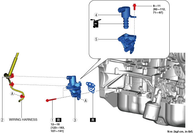
1
|
Engine oil solenoid valve connector
|
|
2
|
Oil pressure switch connector
|
|
3
|
Oil pressure switch
|
|
4
|
Engine oil solenoid valve
|
|
5
|
Gasket
|
Engine oil solenoid valve removal note
1. Cover the area around the engine oil solenoid valve with a rag because a small amount of engine oil will leak from the engine oil solenoid valve installation area.
Engine oil solenoid valve installation note
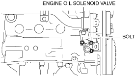
1. After tightening the three bolts shown in the figure, tighten the first tightened bolt to the specified tightening torque again.
am3uuw00008913
|
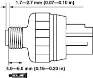
Oil pressure switch installation note
1. When reusing the oil pressure switch, apply silicone sealant (TB1207B or equivalent) to the threads of the oil pressure switch.
am3uuw00008914
|
2. Install the oil pressure switch.
With Coolant Control Valve
1. Disconnect the negative battery terminal. (See NEGATIVE BATTERY TERMINAL DISCONNECTION/CONNECTION.)
2. Remove the front under cover No.2. (See FRONT UNDER COVER No.2 REMOVAL/INSTALLATION.)
3. Remove the front splash shield (RH). (See SPLASH SHIELD REMOVAL/INSTALLATION.)
4. Remove in the order indicated in the table.
5. Install in the reverse order of removal.
6. Start the engine and confirm that there is no oil leakage.
ac5wzw00012157
|
|
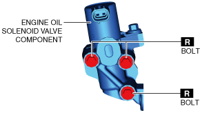
1
|
Bolt
|
|
2
|
Engine oil solenoid valve connector
|
|
3
|
Engine oil solenoid valve component
|
|
4
|
Engine oil solenoid valve
|
|
5
|
Spacer
|
Engine oil solenoid valve removal note
1. Cover the area around the engine oil solenoid valve with a rag because a small amount of engine oil will leak from the engine oil solenoid valve installation area.
Engine oil solenoid valve installation note
1. After tightening the three bolts shown in the figure, tighten the first tightened bolt to the specified tightening torque again.
ac5wzw00012158
|