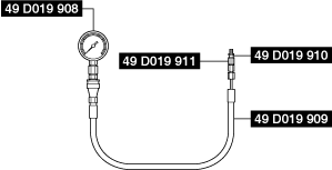
1: 49 D019 908
2: –
Gauge
(Part of 49 D019 9A2)

1: 49 D019 909
2: –
Hose
(Part of 49 D019 9A2)

1: 49 D019 910
2: –
Adapter
(Part of 49 D019 9A2)

1: 49 D019 911
2: –
Adapter
(Part of 49 D019 9A2)

—
—
OIL PRESSURE INSPECTION [WITHOUT CYLINDER DEACTIVATION (SKYACTIV-G 2.0, SKYACTIV-G 2.5)]
id0111m1800300
Special Service Tool (SST)
|
1: 49 D019 908
2: –
Gauge
(Part of 49 D019 9A2)
|
|
1: 49 D019 909
2: –
Hose
(Part of 49 D019 9A2)
|
|
1: 49 D019 910
2: –
Adapter
(Part of 49 D019 9A2)
|
|
|
1: 49 D019 911
2: –
Adapter
(Part of 49 D019 9A2)
|
|
—
|
—
|
||
Without Coolant Control Valve
1. Disconnect the negative battery terminal. (See NEGATIVE BATTERY TERMINAL DISCONNECTION/CONNECTION.)
2. Remove the front under cover No.2. (See FRONT UNDER COVER No.2 REMOVAL/INSTALLATION.)
3. Remove the oil pressure switch. (See ENGINE OIL SOLENOID VALVE REMOVAL/INSTALLATION [WITHOUT CYLINDER DEACTIVATION (SKYACTIV-G 2.0, SKYACTIV-G 2.5)].)
am6zzw00004384
|
4. Install the SSTs to the oil pressure switch installation hole using the following procedure.
5. Connect the negative battery terminal. (See NEGATIVE BATTERY TERMINAL DISCONNECTION/CONNECTION.)
6. Warm up the engine to normal operating temperature.
7. Run the engine at the specified speed, and note the gauge readings.
8. Stop the engine and wait until it is cools.
9. Disconnect the negative battery terminal. (See NEGATIVE BATTERY TERMINAL DISCONNECTION/CONNECTION.)
10. Remove the SSTs.
11. Install the oil pressure switch. (See ENGINE OIL SOLENOID VALVE REMOVAL/INSTALLATION [WITHOUT CYLINDER DEACTIVATION (SKYACTIV-G 2.0, SKYACTIV-G 2.5)].)
12. Connect the negative battery terminal. (See NEGATIVE BATTERY TERMINAL DISCONNECTION/CONNECTION.)
13. Start the engine and confirm that there is no oil leakage.
14. Install the front under cover No.2. (See FRONT UNDER COVER No.2 REMOVAL/INSTALLATION.)
With Coolant Control Valve
1. Connect the M-MDS to the DLC-2.
2. Start the engine and warm it up.
3. Select the engine hydraulic pressure (PID: EOP) and the engine speed (PID: RPM) using the M-MDS data monitor function.
4. Verify the engine hydraulic pressure (PID: EOP) value while the engine maintains a constant speed.