 |
ac5uuw00007049
FUEL-FILLER PIPE REMOVAL/INSTALLATION [WITHOUT CYLINDER DEACTIVATION (SKYACTIV-G 2.0, SKYACTIV-G 2.5)]
id0114m1806900
1. Level the vehicle.
2. Complete the “BEFORE SERVICE PRECAUTION”. (See BEFORE SERVICE PRECAUTION [WITHOUT CYLINDER DEACTIVATION (SKYACTIV-G 2.0, SKYACTIV-G 2.5)].)
3. Drain the fuel. (See FUEL DRAINING PROCEDURE [WITHOUT CYLINDER DEACTIVATION (SKYACTIV-G 2.0, SKYACTIV-G 2.5)].)
4. Open the fuel-filler lid.
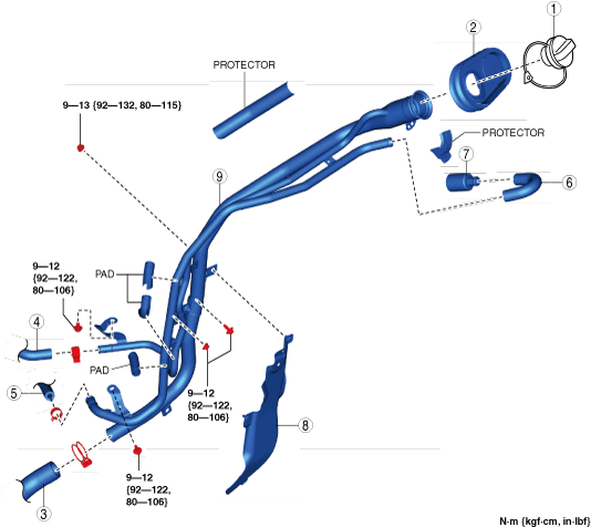
5. Remove in the order indicated in the table.
6. Install in the reverse order of removal.
7. Complete the “AFTER SERVICE PRECAUTION”. (See AFTER SERVICE PRECAUTION [WITHOUT CYLINDER DEACTIVATION (SKYACTIV-G 2.0, SKYACTIV-G 2.5)].)
ac5uuw00007049
|
|
1
|
Fuel-filler cap
|
|
2
|
Dust cover
(See Dust cover removal note.)
|
|
3
|
Joint hose
(See Joint hose installation note.)
|
|
4
|
Breather hose
|
|
5
|
Evaporative hose No.1
|
|
6
|
Evaporative hose No.2
|
|
7
|
Plug
|
|
8
|
Fuel-filler pipe protector
|
|
9
|
Fuel-filler pipe
|
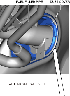
Dust cover removal note
1. Remove the rear mudguard (LH). (See MUDGUARD REMOVAL/INSTALLATION.)
2. Release the dust cover tab using a flathead screwdriver as shown in the figure.
ac5uuw00007047
|
3. Remove the dust cover.
Fuel-filler pipe removal note
1. Remove the rear tire (LH). (See WHEEL AND TIRE SPECIFICATION.)
2. Remove the fuel-filler pipe.
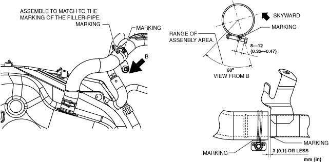
Fuel-filler Pipe Installation Note
1. Temporarily install the fuel-filler pipe to the vehicle-side stud bolt.
ac5uuw00010496
|
2. Temporarily tighten bolt A.
3. Completely tighten bolt B.
4. Completely tighten bolt C.
5. Completely tighten bolt A.
6. Completely tighten the nut.
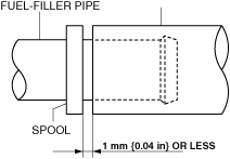
Evaporative hose no.1 installation note
1. Install the evaporative hose No.1 as shown in the figure.
ac5uuw00010808
|
Breather hose installation note
1. Install the breather hose as shown in the figure.
ac5wzw00013705
|
Joint hose installation note
1. Install the joint hose as shown in the figure.
ac5wzw00013083
|