 |
ac5uuw00010510
EXHAUST SYSTEM REMOVAL/INSTALLATION [SKYACTIV-G 2.5T]
id0115q4800200
Replacement Part
|
Gasket
Quantity: 1
Location of use: Main silencer
|
Nut
Quantity: 4
Location of use: TWC
|
Gasket
Quantity: 2
Location of use: WU-TWC
|
|
Nut
Quantity: 5
Location of use: WU-TWC
|
Gasket
Quantity: 1
Location of use: Dynamic pressure turbo
|
Nut
Quantity: 6
Location of use: Exhaust manifold
|
|
Gasket
Quantity: 1
Location of use: Exhaust manifold
|
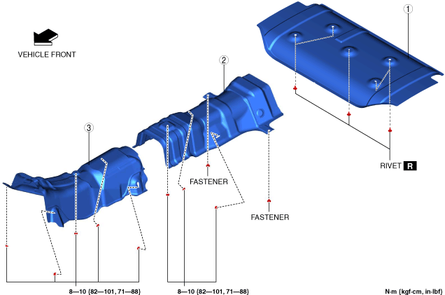
RIVET
Quantity: 5
Location of use: Insulator (rear)
|
—
|
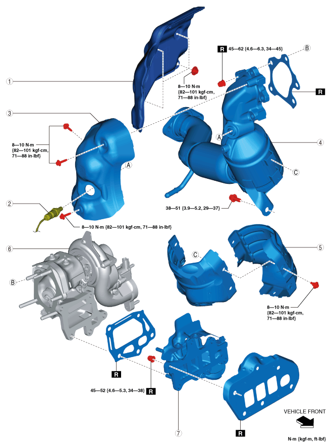
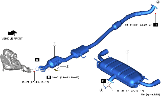
Exhaust System Removal/Installation
1. Disconnect the negative battery terminal. (See NEGATIVE BATTERY TERMINAL DISCONNECTION/CONNECTION.)
2. Remove in the order indicated in the table.
3. Remove the insulator. (See Exhaust System Insulator Removal/Installation.)
4. Install in the reverse order of removal.
Step 1
ac5uuw00010510
|
|
1
|
Main silencer
|
|
2
|
HO2S
|
|
3
|
TWC
|
Step 2
ac5wzw00014318
|
|
1
|
Insulator
(See Insulator removal note.)
(See Insulator installation note.)
|
|
2
|
A/F sensor
|
|
3
|
WU-TWC insulator No.1
|
|
4
|
WU-TWC
(See WU-TWC installation note.)
|
|
5
|
WU-TWC insulator No.2
|
|
6
|
Dynamic pressure turbo
|
|
7
|
Exhaust manifold
|
Insulator removal note
1. Remove the plug hole plate. (See PLUG HOLE PLATE REMOVAL/INSTALLATION [SKYACTIV-G 2.5T].)
2. Remove the cowl panel. (See COWL PANEL REMOVAL/INSTALLATION.)
3. Remove the front crossmember. (See FRONT CROSSMEMBER REMOVAL/INSTALLATION.)
4. Remove the insulator.
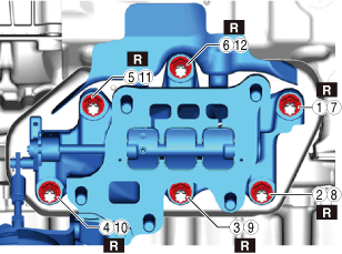
Exhaust manifold installation note
1. Tighten the nuts in the order shown in the figure.
ac5uuw00010552
|
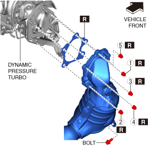
WU-TWC installation note
1. Temporarily tighten the WU-TWC installation nuts.
ac5uuw00010553
|
2. Tighten the WU-TWC installation nuts in the order shown in the figure to the specified torque.
3. Temporarily tighten the WU-TWC installation bolt.
4. Tighten the WU-TWC installation bolt to the specified torque.
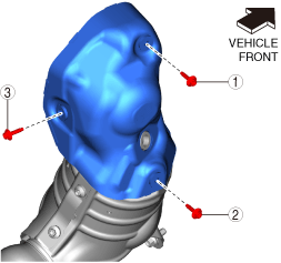
WU-TWC insulator No.1 installation note
1. Temporarily tighten the WU-TWC insulator No.1 installation bolts.
ac9uuw00009494
|
2. Tighten the bolts in the order shown in the figure.
Insulator installation note
1. Install the insulator.
2. Install the front crossmember. (See FRONT CROSSMEMBER REMOVAL/INSTALLATION.)
3. Install the cowl panel. (See COWL PANEL REMOVAL/INSTALLATION.)
4. Install the plug hole plate. (See PLUG HOLE PLATE REMOVAL/INSTALLATION [SKYACTIV-G 2.5T].)
Exhaust System Insulator Removal/Installation
1. Remove the propeller shaft. (See PROPELLER SHAFT REMOVAL/INSTALLATION.)
2. Remove in the order indicated in the table.
3. Install in the reverse order of removal.
ac5uuw00010511
|
|
1
|
Insulator (rear)
|
|
2
|
Insulator (middle)
|
|
3
|
Insulator (front)
|
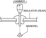
Insulator (rear) removal note
1. Push out the mandrel using a hammer and punch (2—2.8 mm {0.08—0.11 in} diameter).
ac5uuw00000434
|
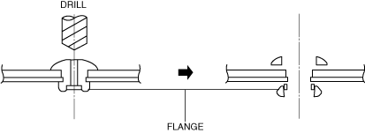
2. Remove the flange using a drill (5 mm {0.20 in} drill bit).
ar8uuw00001479
|
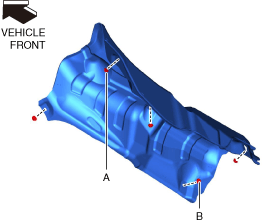
Insulator (front) installation note
1. Tighten nut A shown in the figure to the specified torque.
ac5uuw00010507
|
2. Tighten nut B shown in the figure to the specified torque.
3. Tighten the remaining nuts to the specified torque.
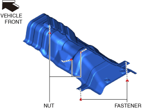
Insulator (middle) installation note
1. Install the fasteners shown in the figure.
ac5uuw00010508
|
2. Tighten the nuts shown in the figure to the specified torque.
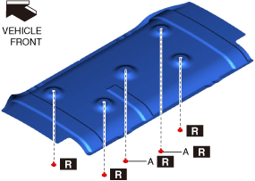
Insulator (rear) installation note
1. Install rivets A shown in the figure.
ac5uuw00010509
|
2. Install the remaining rivets.