 |
am3uuw00008598
PURGE SOLENOID VALVE REMOVAL/INSTALLATION [WITHOUT CYLINDER DEACTIVATION (SKYACTIV-G 2.0, SKYACTIV-G 2.5)]
id0116m1804300
1. Disconnect the negative battery terminal. (See NEGATIVE BATTERY TERMINAL DISCONNECTION/CONNECTION.)
2. Remove the plug hole plate. (See PLUG HOLE PLATE REMOVAL/INSTALLATION [WITHOUT CYLINDER DEACTIVATION (SKYACTIV-G 2.0, SKYACTIV-G 2.5)].)
3. Remove the air cleaner and air hose as a single unit. (See INTAKE-AIR SYSTEM REMOVAL/INSTALLATION [WITHOUT CYLINDER DEACTIVATION (SKYACTIV-G 2.0, SKYACTIV-G 2.5)].)
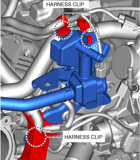
4. Disconnect the high pressure fuel pump connector.
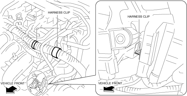
5. Disconnect the harness clip as shown in the figure.
am3uuw00008598
|
6. Disconnect the vacuum hose from the intake manifold. (See INTAKE-AIR SYSTEM REMOVAL/INSTALLATION [WITHOUT CYLINDER DEACTIVATION (SKYACTIV-G 2.0, SKYACTIV-G 2.5)].)
7. Disconnect the harness clip as shown in the figure. (With coolant control valve)
ac5wzw00012240
|
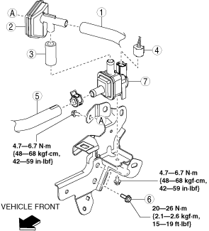
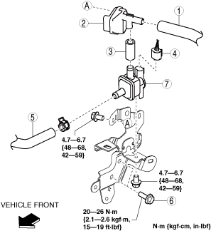
8. Remove in the order indicated in the table.
SKYACTIV-G 2.0 (Without coolant control valve)
ac5uuw00002695
|
SKYACTIV-G 2.5 (Without coolant control valve)
am6zzw00010421
|
|
1
|
Evaporative hose No.1
|
|
2
|
Catch tank
|
|
3
|
Evaporative hose No.2
|
|
4
|
Purge solenoid valve connector
|
|
5
|
Evaporative hose No.3
|
|
6
|
Purge solenoid valve bracket installation bolt
|
|
7
|
Purge solenoid valve
|
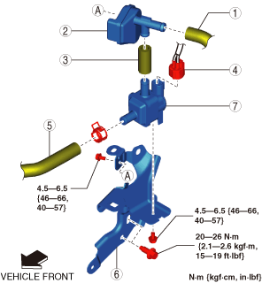
SKYACTIV-G 2.0, SKYACTIV-G 2.5 (With coolant control valve)
ac5wzw00013233
|
|
1
|
Evaporative hose No.1
|
|
2
|
Catch tank
|
|
3
|
Evaporative hose No.2
|
|
4
|
Purge solenoid valve connector
|
|
5
|
Evaporative hose No.3
|
|
6
|
Purge solenoid valve bracket
|
|
7
|
Purge solenoid valve
|
9. Install in the reverse order of removal.
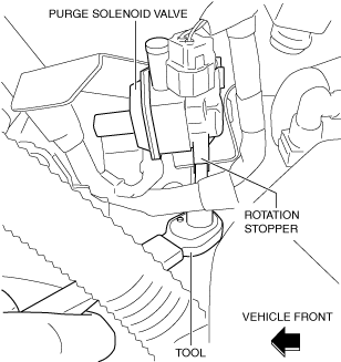
Purge Solenoid Valve Installation Note (Without coolant control valve)
1. Temporarily install the purge solenoid valve to the bracket.
2. Lift up and tighten the purge solenoid valve as shown in the figure.
am3uuw00008599
|
Evaporative Hose No.3 Installation Note
1. Install the evaporative hose No.3 as shown in the figure.
am3uuw00008528
|
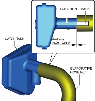
Evaporative Hose No.1 Installation Note
1. Install the evaporative hose No.1 as shown in the figure.
ac5uuw00007799
|
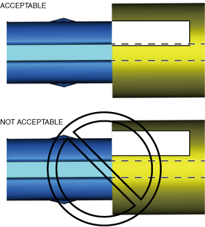
2. Verify that a portion of the mark on evaporative hose No. 1 is covering the catch tank projection area.
ac5uuw00007800
|