 |
am3zzw00012840
MASS AIR FLOW (MAF) SENSOR INSPECTION [WITHOUT CYLINDER DEACTIVATION (SKYACTIV-G 2.0, SKYACTIV-G 2.5)]
id0140m1800700
Without Coolant Control Valve
Visual Inspection
1. Disconnect the negative battery terminal. (See NEGATIVE BATTERY TERMINAL DISCONNECTION/CONNECTION.)
2. Disconnect the MAF sensor/IAT sensor No.1 connector.
3. Remove the MAF sensor/IAT sensor No.1. (See MASS AIR FLOW (MAF) SENSOR/INTAKE AIR TEMPERATURE (IAT) SENSOR NO.1 REMOVAL/INSTALLATION [WITHOUT CYLINDER DEACTIVATION (SKYACTIV-G 2.0, SKYACTIV-G 2.5)].)
4. Visually inspect the MAF sensor for the following:
Function Inspection
1. Connect the M-MDS to the DLC-2.
2. Switch the ignition ON (engine off).
3. Display the PID MAF. (See ON-BOARD DIAGNOSTIC TEST [PCM (WITHOUT CYLINDER DEACTIVATION (SKYACTIV-G 2.0, SKYACTIV-G 2.5))].) (See PCM INSPECTION [WITHOUT CYLINDER DEACTIVATION (SKYACTIV-G 2.0, SKYACTIV-G 2.5)].)
4. Compare the voltage and flow rate indications for the PID MAF with the standard in the table indicated below.
Standard
|
MAF |
Remarks |
|
|---|---|---|
|
V |
g/s {lb/min} |
|
|
Approx. 0.72
|
0.59 {0.078}
|
Ignition switched ON (engine off)
|
|
Approx. 0.93
|
3.79 {0.501}
|
Idle (after warm up)
|
|
Approx. 1.11
|
6.96 {0.921}
|
Racing (Engine speed: 2,000 rpm)
|
Voltage Inspection
1. Disconnect the negative battery terminal. (See NEGATIVE BATTERY TERMINAL DISCONNECTION/CONNECTION.)
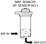
2. Remove the MAF sensor/IAT sensor No.1 without disconnecting the connector. (See MASS AIR FLOW (MAF) SENSOR/INTAKE AIR TEMPERATURE (IAT) SENSOR NO.1 REMOVAL/INSTALLATION [WITHOUT CYLINDER DEACTIVATION (SKYACTIV-G 2.0, SKYACTIV-G 2.5)].)
3. Reconnect the negative battery terminal. (See NEGATIVE BATTERY TERMINAL DISCONNECTION/CONNECTION.)
4. Connect the M-MDS to the DLC-2.
5. Switch the ignition ON (engine off).
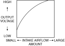
6. As the air gradually approaches the MAF detection part of the MAF sensor/IAT sensor No.1, verify that the MAF sensor output voltage (PID: MAF) varies. (See ON-BOARD DIAGNOSTIC TEST [PCM (WITHOUT CYLINDER DEACTIVATION (SKYACTIV-G 2.0, SKYACTIV-G 2.5))].) (See PCM REMOVAL/INSTALLATION [WITHOUT CYLINDER DEACTIVATION (SKYACTIV-G 2.0, SKYACTIV-G 2.5)].)
am3zzw00012840
|
Specification
ac5uuw00003020
|
With Coolant Control Valve
Visual inspection
1. Disconnect the negative battery terminal. (See NEGATIVE BATTERY TERMINAL DISCONNECTION/CONNECTION.)
2. Disconnect the MAF sensor/IAT sensor No.1 connector.
3. Remove the MAF sensor/IAT sensor No.1. (See MASS AIR FLOW (MAF) SENSOR/INTAKE AIR TEMPERATURE (IAT) SENSOR NO.1 REMOVAL/INSTALLATION [WITHOUT CYLINDER DEACTIVATION (SKYACTIV-G 2.0, SKYACTIV-G 2.5)].)
4. Visually inspect the MAF sensor for the following:
Function inspection
1. Connect the M-MDS to the DLC-2.
2. Switch the ignition ON (engine off).
3. Display the PID MAF. (See ON-BOARD DIAGNOSTIC TEST [PCM (WITHOUT CYLINDER DEACTIVATION (SKYACTIV-G 2.0, SKYACTIV-G 2.5))].) (See PCM REMOVAL/INSTALLATION [WITHOUT CYLINDER DEACTIVATION (SKYACTIV-G 2.0, SKYACTIV-G 2.5)].)
4. Compare the voltage and flow rate indications for the PID MAF with the standard in the table indicated below.
Standard
|
MAF |
Remarks |
|
|---|---|---|
|
V |
g/s {lb/min} |
|
|
Approx. 1.69
|
0.00 {0.000}
|
Ignition switched ON (engine off)
|
|
Approx. 1.89
|
2.50 {0.331}
|
Idle (after warm up)
|
|
Approx. 2.02
|
3.80 {0.503}
|
Racing (Engine speed: 2,000 rpm)
|