|
ac5uuw00006401
SHIFT CONTROL MODULE REMOVAL/INSTALLATION [C66M-R, C66MX-R]
id0515ma160200
Replacement Part
|
Gasket
Quantity: 1
Location of use: Detent ball pin
|
Breather
Quantity: 1
Location of use: Shift control module
|
O-ring
Quantity: 1
Location of use: Shift control module
|
1. Shift the shift lever to the neutral position.
2. Disconnect the negative battery terminal. (See NEGATIVE BATTERY TERMINAL DISCONNECTION/CONNECTION.)
3. Remove the following parts.
4. Disconnect the control cable from the manual transaxle. (See CONTROL CABLE REMOVAL/INSTALLATION [C66M-R, C66MX-R].) (See Control Cable Ends (Transaxle Side) Installation Note.)
5. Remove the neutral switch. (See NEUTRAL SWITCH REMOVAL/INSTALLATION [C66M-R, C66MX-R].)
6. Remove the detent ball pin in the order shown in the figure.
ac5uuw00006401
|
|
1
|
Plug
|
|
2
|
Gasket
|
|
3
|
Spring
|
|
4
|
Detent ball pin
|
7. Remove the back-up light switch. (See BACK-UP LIGHT SWITCH REMOVAL/INSTALLATION [C66M-R, C66MX-R].)
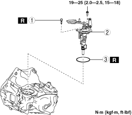
8. Remove the shift control module in the order shown in the figure.
ac5uuw00006402
|
|
1
|
Breather
|
|
2
|
Shift control module
|
|
3
|
O-ring
|
9. Install in the reverse order of removal.
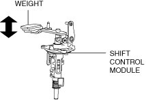
Shift Control Module Installation Note
1. Verify that the shift control module is in the neutral position.
ac5uuw00002962
|
2. Install the shift control module.
Control Cable Ends (Transaxle Side) Installation Note
1. Verify that the shift control module is in the neutral position.
2. Connect the control cable to the manual transaxle. (See CONTROL CABLE REMOVAL/INSTALLATION [C66M-R, C66MX-R].)
3. Make sure that the shift lever can be shifted smoothly.