 |
ac5wzw00010741
OIL COOLER REMOVAL/INSTALLATION [GW6A-EL, GW6AX-EL (SKYACTIV-D 2.2)]
id0517i21175i8
Replacement Part
|
O-ring
Quantity: 2
Location of use: Oil cooler
|
Gasket
Quantity: 2
Location of use: Connector bolt
|
Water Hose
1. Set the coolant reserve tank aside with the hose connected. (See COOLANT RESERVE TANK REMOVAL/INSTALLATION [SKYACTIV-D 2.2].)
2. Remove the front under cover No.2. (See FRONT UNDER COVER No.2 REMOVAL/INSTALLATION.)
3. Drain the engine coolant. (See ENGINE COOLANT REPLACEMENT [SKYACTIV-D 2.2].)
4. Remove in the order indicated in the table.
5. Install in the reverse order of removal.
6. Add the engine coolant. (See ENGINE COOLANT REPLACEMENT [SKYACTIV-D 2.2].)
ac5wzw00010741
|
|
1
|
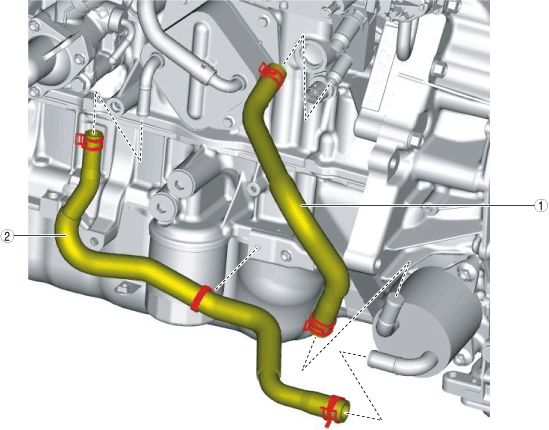
Water hose No.1
|
|
2
|
Water hose No.2
|
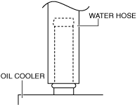
Water hose No.1 and No.2 (oil cooler side) installation note
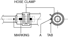
1. Install the water hose to the oil cooler as shown in the figure with the hose clamp expanded.
am3uuw00008323
|
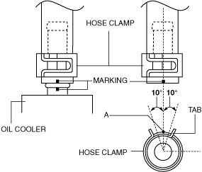
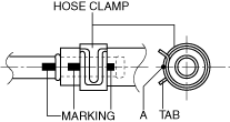
2. Install the hose clamp so that center A of the hose clamp tab is within the range shown in the figure.
Water hose No.1
ac5wzw00003719
|
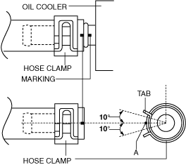
Water hose No.2
ac5wzw00003718
|
3. Verify that the hose clamp does not interfere with any other components.
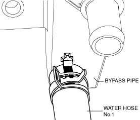
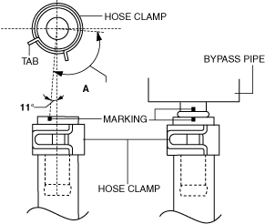
Water hose No.1 (bypass pipe side) installation note
1. Install the water hose to the bypass pipe as shown in the figure with the hose clamp expanded.
ac5wzw00009238
|
2. The hose clamp installation direction is within range A shown in the figure.
ac5wzw00009239
|
3. Verify that the hose clamp does not interfere with any other components.
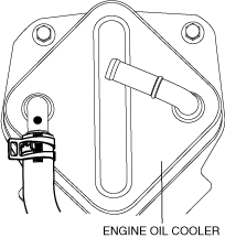
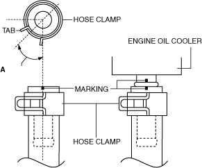
Water hose No.2 (engine oil cooler side) installation note
1. Install the water hose to the engine oil cooler as shown in the figure with the hose clamp expanded.
ac5wzw00009240
|
2. The hose clamp installation direction is within range A shown in the figure.
ac5wzw00009241
|
3. Verify that the hose clamp does not interfere with any other components.
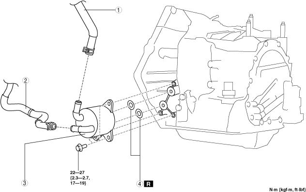
Oil Cooler (Without oil cooler No.2)
1. Remove the front under cover No.2. (See FRONT UNDER COVER No.2 REMOVAL/INSTALLATION.)
2. Drain the ATF. (See AUTOMATIC TRANSAXLE FLUID (ATF) REPLACEMENT [GW6A-EL, GW6AX-EL].)
3. Drain the engine coolant. (See ENGINE COOLANT REPLACEMENT [SKYACTIV-D 2.2].)
4. Remove in the order indicated in the table.
5. Install in the reverse order of removal.
6. Add the engine coolant. (See ENGINE COOLANT REPLACEMENT [SKYACTIV-D 2.2].)
7. Add the ATF. (See AUTOMATIC TRANSAXLE FLUID (ATF) REPLACEMENT [GW6A-EL, GW6AX-EL].)
8. Perform the “Mechanical System Test”. (See MECHANICAL SYSTEM TEST [GW6A-EL, GW6AX-EL].)
ac5wzw00009242
|
|
1
|
Water hose No.1
|
|
2
|
Water hose No.2
|
|
3
|
Water-cooled oil cooler
|
|
4
|
O-rings
|
Water hose No.1 and No.2 (oil cooler side) installation note
1. Install the water hose to the oil cooler as shown in the figure with the hose clamp expanded.
am3uuw00008323
|
2. Install the hose clamp so that center A of the hose clamp tab is within the range shown in the figure.
Water hose No.1
ac5wzw00003719
|
Water hose No.2
ac5wzw00003718
|
3. Verify that the hose clamp does not interfere with any other components.
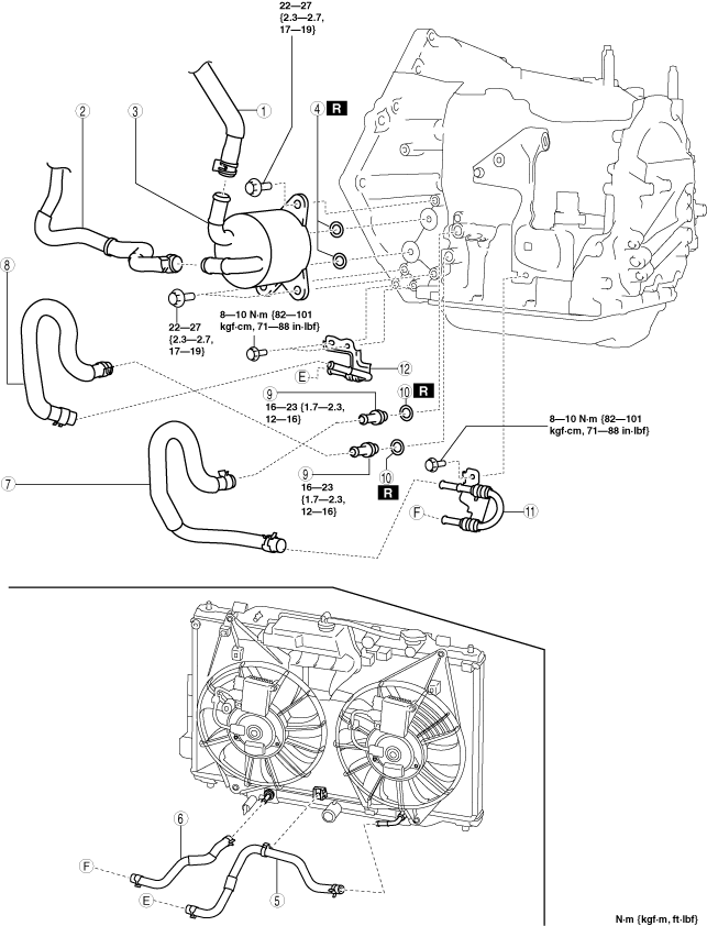
Oil Cooler (With oil cooler No.2)
1. Remove the front under cover No.2. (See FRONT UNDER COVER No.2 REMOVAL/INSTALLATION.)
2. Drain the ATF. (See AUTOMATIC TRANSAXLE FLUID (ATF) REPLACEMENT [GW6A-EL, GW6AX-EL].)
3. Drain the engine coolant. (See ENGINE COOLANT REPLACEMENT [SKYACTIV-D 2.2].)
4. Remove in the order indicated in the table.
5. Install in the reverse order of removal.
6. Add the engine coolant. (See ENGINE COOLANT REPLACEMENT [SKYACTIV-D 2.2].)
7. Add the ATF. (See AUTOMATIC TRANSAXLE FLUID (ATF) REPLACEMENT [GW6A-EL, GW6AX-EL].)
8. Perform the “Mechanical System Test”. (See MECHANICAL SYSTEM TEST [GW6A-EL, GW6AX-EL].)
ac5wzw00009243
|
|
1
|
Water hose No.1
|
|
2
|
Water hose No.2
|
|
3
|
Water-cooled oil cooler
|
|
4
|
O-rings
|
|
5
|
Oil hose No.1
|
|
6
|
Oil hose No.2
|
|
7
|
Oil hose No.3
|
|
8
|
Oil hose No.4
|
|
9
|
Connector bolt
|
|
10
|
Gasket
|
|
11
|
Oil pipe No.1
|
|
12
|
Oil pipe No.2
|
Water hose No.1 and No.2 (oil cooler side) installation note
1. Install the water hose to the oil cooler as shown in the figure with the hose clamp expanded.
am3uuw00008323
|
2. Install the hose clamp so that center A of the hose clamp tab is within the range shown in the figure.
Water hose No.1
ac5wzw00003719
|
Water hose No.2
ac5wzw00003718
|
3. Verify that the hose clamp does not interfere with any other components.
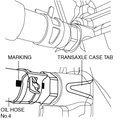
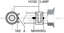
Oil hose No.4 (oil pipe No.2 side) installation note
1. Install the oil hose No.4 to the oil pipe No.2 as shown in the figure with the hose clamp expanded.
ac5wzw00009244
|
2. Install the hose clamp so that center A of the hose clamp tab is aligned with the marking as shown in the figure.
ac5wzw00009245
|
3. Verify that the hose clamp does not interfere with any other components.
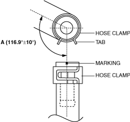
Oil hose No.4 (transaxle side) installation note
1. Install the oil hose No.4 to the connector bolt as shown in the figure with the hose clamp expanded.
ac5wzw00009246
|
2. The hose clamp installation direction is within range A shown in the figure.
ac5wzw00009247
|
3. Verify that the hose clamp does not interfere with any other components.
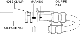
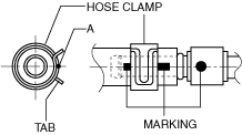
Oil hose No.3 (oil pipe No.1 side) installation note
1. Install the oil hose No.3 to the oil pipe No.1 as shown in the figure with the hose clamp expanded.
ac5wzw00009248
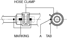
|
2. Install the hose clamp so that center A of the hose clamp tab is aligned with the marking as shown in the figure.
ac5wzw00009249
|
3. Verify that the hose clamp does not interfere with any other components.
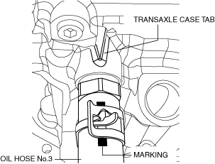
Oil hose No.3 (transaxle side) installation note
1. Install the oil hose No.3 to the connector bolt as shown in the figure with the hose clamp expanded.
ac5wzw00009250
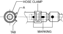
|
2. The hose clamp installation direction is within range A shown in the figure.
ac5wzw00009251
|
3. Verify that the hose clamp does not interfere with any other components.
Oil hose No.2 (oil pipe No.1 side) installation note
1. Install the oil hose No.2 to the oil pipe No.1 as shown in the figure with the hose clamp expanded.
ac5wzw00009252
|
2. Install the hose clamp so that center A of the hose clamp tab is aligned with the marking as shown in the figure.
ac5wzw00009253
|
3. Verify that the hose clamp does not interfere with any other components.
Oil hose No.2 (radiator inside) installation note
1. Install the oil hose No.2 to the radiator as shown in the figure with the hose clamp expanded.
ac5wzw00009254
|
2. Install the hose clamp so that center A of the hose clamp tab is aligned with the marking as shown in the figure.
ac5wzw00009623
|
3. Verify that the hose clamp does not interfere with any other components.
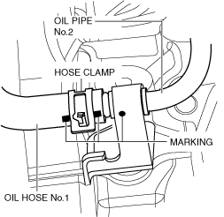
Oil hose No.1 (oil pipe No.2 side) installation note
1. Install the oil hose No.1 to the oil pipe No.2 as shown in the figure with the hose clamp expanded.
ac5wzw00009255
|
2. Install the hose clamp so that center A of the hose clamp tab is aligned with the marking as shown in the figure.
ac5wzw00009256
|
3. Verify that the hose clamp does not interfere with any other components.
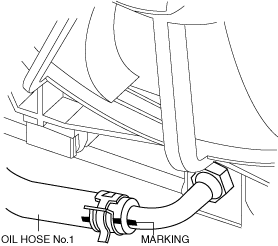
Oil hose No.1 (radiator outside) installation note
1. Install the oil hose No.1 to the radiator as shown in the figure with the hose clamp expanded.
ac5wzw00009257
|
2. Install the hose clamp so that center A of the hose clamp tab is aligned with the marking as shown in the figure.
ac5wzw00003722
|
3. Verify that the hose clamp does not interfere with any other components.