49 JP02 001
Adjustable wrench

49 T025 001
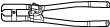
Boot clamp crimpers
STEERING GEAR AND LINKAGE ASSEMBLY
id061300802100
Special Service Tool (SST)
|
49 JP02 001
Adjustable wrench
|
|
49 T025 001
Boot clamp crimpers
|
|
Replacement Part
|
Boot band
Quantity: 2
Location of use: Boot
|
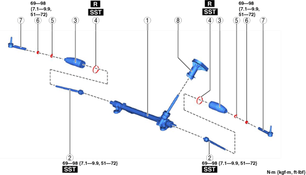
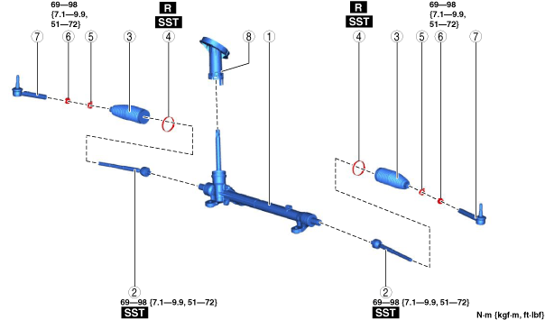
1. Assemble in the order shown in the figure.
2. Install the steering gear and linkage. (See STEERING GEAR AND LINKAGE REMOVAL/INSTALLATION.)
L.H.D.
ac5uuw00006396
|
R.H.D.
ac5wzw00012796
|
|
1
|
Steering gear
|
|
2
|
Tie Rod
(See Tie Rod Assembly Note.)
|
|
3
|
Boot
|
|
4
|
Boot band
(See Boot Band Assembly Note.)
|
|
5
|
Boot clamp
|
|
6
|
Locknut
|
|
7
|
Tie-rod end
(See Tie-rod End Assembly Note.)
|
|
8
|
Dust cover
|
Tie Rod Assembly Note
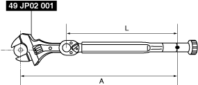
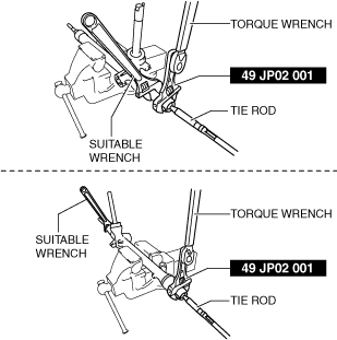
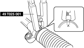
1. Install the SST to the torque wrench as shown in the figure, set it on the tie rod, and measure dimensions A and L shown in the figure.
adejjw00015170
|
2. Tighten the tie rod after calculating the tightening torque using the following formula.
ac5uuw00006397
|
Boot Band Assembly Note
1. Assemble the boot band to the boot.
2. Crimp the boot band using the SST.
ac5jjw00002709
|
3. Verify that the crimping clearance A is within the specification.
4. Rotate the by hand and verify that it is securely installed to the boot band.
Tie-rod End Assembly Note
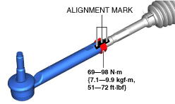
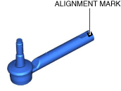
1. Align the alignment marks made before removal and assemble the tie-rod end to the tie rod.
ac5uuw00006398
|
ac5uuw00006399
|
2. Adjust dimension A shown in the figure to the standard, then assemble the tie-rod end.
ac5wzw00013820
|