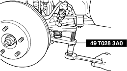
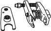
49 T028 3A0
Ball joint puller set
STEERING GEAR AND LINKAGE REMOVAL/INSTALLATION
id061300801700
Special Service Tool (SST)
|
49 T028 3A0
Ball joint puller set
|
|
1. Remove the wheels and tires. (See WHEEL AND TIRE REMOVAL/INSTALLATION.)
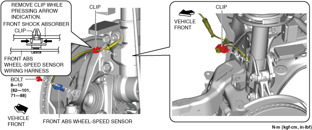
2. Disconnect the front ABS wheel-speed sensor wiring harness installed to the steering knuckle and set it aside. (See FRONT ABS WHEEL-SPEED SENSOR REMOVAL/INSTALLATION.)
ac5uuw00006380
|
3. Remove the following parts.
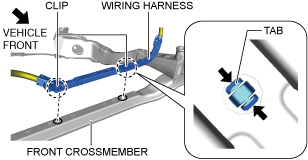
4. Disconnect the wiring harness from the front crossmember. (With i-ELOOP)
ac5wzw00011233
|
5. Detach the tie-rod end from the steering knuckle using the SST. (See TIE-ROD END REPLACEMENT.)
ac5uuw00000134
|
6. Disconnect the front lower arm ball joint from the steering knuckle. (See FRONT LOWER ARM REMOVAL/INSTALLATION.)
7. Remove the insulator. (2WD) (See EXHAUST SYSTEM REMOVAL/INSTALLATION [WITHOUT CYLINDER DEACTIVATION (SKYACTIV-G 2.0, SKYACTIV-G 2.5)].) (See EXHAUST SYSTEM REMOVAL/INSTALLATION [WITH CYLINDER DEACTIVATION (SKYACTIV-G 2.0, SKYACTIV-G 2.5)].) (See EXHAUST SYSTEM REMOVAL/INSTALLATION [SKYACTIV-D 2.2].)
8. Remove the insulator. (4WD) (See FRONT CROSSMEMBER REMOVAL/INSTALLATION.)
9. Remove the joint cover. (See STEERING WHEEL AND COLUMN REMOVAL/INSTALLATION.)
10. Disconnect the intermediate shaft from the steering gear and linkage. (See STEERING WHEEL AND COLUMN REMOVAL/INSTALLATION.)
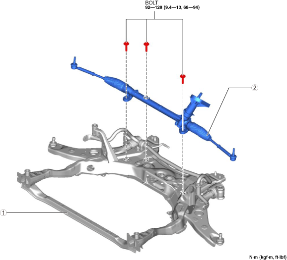
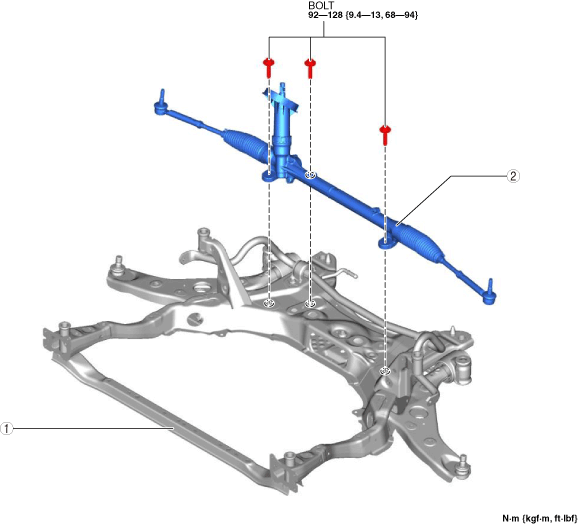
11. Remove in the order indicated in the table.
12. Install in the reverse order of removal.
13. After installation, inspect the front wheel alignment and adjust it if necessary. (See FRONT WHEEL ALIGNMENT.)
L.H.D.
ac5uuw00006381
|
R.H.D.
ac5wzw00009626
|
|
1
|
Front crossmember component
|
|
2
|
Steering gear and linkage
|
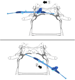
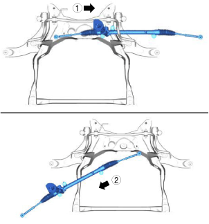
Steering Gear and Linkage Removal Note
1. Remove the steering gear and linkage installation bolts, move the steering gear and linkage in the direction and order of the arrows shown in the figure, and then remove it.
L.H.D.
ac5uuw00006382
|
R.H.D.
ac5jjw00010399
|