 |
ac5wzw00011129
FRONT FENDER STAY REMOVAL/INSTALLATION
id091000803900
Front Fender Stay (LH)
1. Disconnect the negative battery terminal. (See NEGATIVE BATTERY TERMINAL DISCONNECTION/CONNECTION.)
2. Remove the following parts:
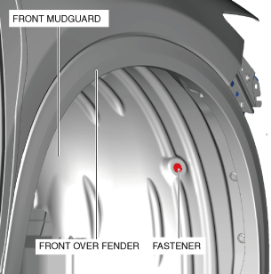
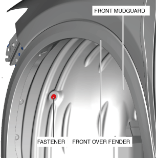
3. Remove the fastener.
ac5wzw00011129
|
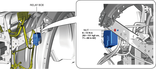
4. Remove the nut.
ac5wzw00011130
|
5. Remove the relay box.
6. Remove the wiring harness clips.
ac5wzw00011131
|
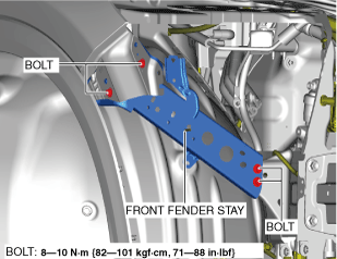
7. Remove the bolts.
ac5wzw00011132
|
8. Remove the front fender stay (LH).
9. Install in the reverse order of removal. (See Front Fender Stay Paint Note.)
Front Fender Stay (RH)
1. Disconnect the negative battery terminal. (See NEGATIVE BATTERY TERMINAL DISCONNECTION/CONNECTION.)
2. Remove the following parts:
3. Remove the fastener.
ac5wzw00011133
|
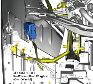
4. Remove the ground bolts.
ac5wzw00011134
|
5. Remove the grounds.
6. Remove the bolts.
ac5wzw00011135
|
7. Remove the front fender stay (RH).
8. Install in the reverse order of removal. (See Front Fender Stay Paint Note.)
Front Fender Stay Paint Note