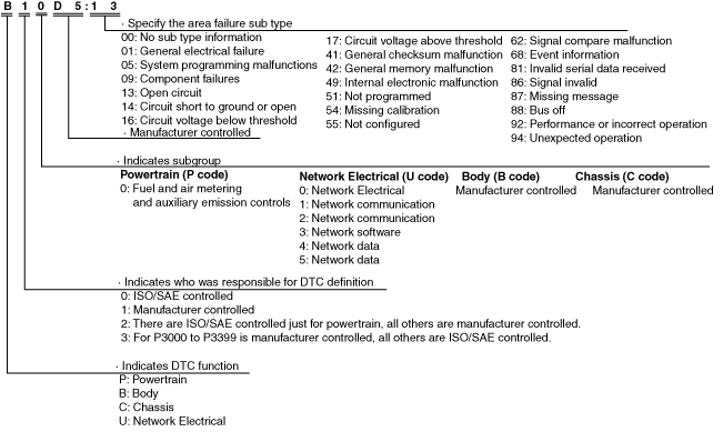
ON-BOARD DIAGNOSTIC SYSTEM [AUTO LEVELING CONTROL MODULE]
id0918001121b0
Outline
Function
Malfunction detection function
DTC table
DTC No. |
LED headlight warning light |
Description |
Fail-safe function |
Drive cycle |
Self test type*1 |
Memory function |
---|---|---|---|---|---|---|
B1041:14
|
ON
|
Headlight leveling actuator circuit malfunction
|
×
|
—
|
D
|
×
|
B1D00:13
|
ON
|
Headlight (LH) circuit malfunction
|
×
|
—
|
C, D
|
×
|
B1D01:13
|
ON
|
Headlight (RH) circuit malfunction
|
×
|
—
|
C, D
|
×
|
C0061:54
|
Flash
|
Acceleration sensor initial position learning not completed
|
×
|
—
|
D
|
×
|
U0001:88
|
ON
|
Unit communication error (HS-CAN)
|
×
|
—
|
C, D
|
×
|
U0100:00
|
ON
|
Communication error with PCM
|
×
|
—
|
C, D
|
×
|
U0140:00
|
ON
|
Communication error with front body control module (FBCM)
|
×
|
—
|
C, D
|
×
|
U0155:00
|
ON*2
|
Communication error with instrument cluster
|
×
|
—
|
C, D
|
×
|
U0423:68
|
—
|
Error signal received from instrument cluster
|
×
|
—
|
C, D
|
—
|
U2005:86
|
ON
|
Error signal received from PCM
|
×
|
—
|
C, D
|
×
|
U2300:54
|
ON
|
Configuration data not received from instrument cluster
|
×
|
—
|
C, D
|
×
|
U2300:55
|
—
|
Instrument cluster configuration not implemented
|
×
|
—
|
C, D
|
×
|
U2300:56
|
ON
|
Configuration data unmatched with instrument cluster
|
×
|
—
|
C, D
|
×
|
U3000:42
|
ON
|
Auto leveling control module internal malfunction
|
×
|
—
|
C, D
|
×*3
|
U3000:49
|
ON*2
|
Auto leveling control module internal malfunction
|
×
|
—
|
C, D
|
×*3
|
U3003:16
|
ON
|
Auto leveling control module low power supply voltage input
|
×
|
—
|
C, D
|
×
|
U3003:17
|
ON
|
Auto leveling control module high power supply voltage input
|
×
|
—
|
C, D
|
×
|
DTC 7-digit code definition
ac5wzn00004035
|
Status byte for DTC
ac5uun00003034
|
Detection condition for the applicable DTC
DTC No. |
Description |
Detection condition |
---|---|---|
B1041:14
|
Headlight leveling actuator circuit malfunction
|
• Headlight leveling actuator circuit voltage of 3.2 V or less is detected for 5 s or more with the ignition switched ON (engine off or on).
|
B1D00:13
|
Headlight (LH) circuit malfunction
|
• The auto leveling control module detected an open circuit in the headlight (LH) circuit during the headlight LO on control for 5 s or more with the ignition switched ON (engine off or on).
|
B1D01:13
|
Headlight (RH) circuit malfunction
|
• The auto leveling control module detected an open circuit in the headlight (RH) circuit during the headlight LO on control for 5 s or more with the ignition switched ON (engine off or on).
|
C0061:54
|
Acceleration sensor initial position learning not completed
|
• The auto leveling control module detects that the acceleration sensor initial position learning is not completed.
|
U0001:88
|
Unit communication error (HS-CAN)
|
• The auto leveling control module detected CAN bus communication line (HS-CAN) malfunction ten times continuously.
|
U0100:00
|
Communication error with PCM
|
• The auto leveling control module could not receive CAN signal from the PCM for 5 s or more.
|
U0140:00
|
Communication error with front body control module (FBCM)
|
• The auto leveling control module could not receive CAN signal from the front body control module (FBCM) for 5 s or more.
|
U0155:00
|
Communication error with instrument cluster
|
• The auto leveling control module could not receive CAN signal from the instrument cluster for 5 s or more.
|
U0423:68
|
Error signal received from instrument cluster
|
• Auto leveling control module received the error signals from the instrument cluster for 5 s or more with the ignition switched ON (engine off or on).
|
U2005:86
|
Error signal received from PCM
|
• The auto leveling control module received vehicle speed signal error from the PCM for 5 s or more with the ignition switched ON (engine off or on).
|
U2300:54
|
Configuration data not received from instrument cluster
|
• After 30 s or more have elapsed with the ignition switched ON (engine on or off), the auto leveling control module cannot receive the configuration data from the instrument cluster.
|
U2300:55
|
Instrument cluster configuration not implemented
|
• The auto leveling control module received a signal which indicates the instrument cluster configuration is not performed.
|
U2300:56
|
Configuration data unmatched with instrument cluster
|
• Configuration data of the auto leveling control module and instrument cluster are not matched.
|
U3000:42
|
Auto leveling control module internal malfunction
|
• Auto leveling control module detects the internal EEPROM malfunction.
|
U3000:49
|
Auto leveling control module internal malfunction
|
• The auto leveling control module detects the internal malfunction with the ignition switched ON (engine off or on).
|
U3003:16
|
Auto leveling control module low power supply voltage input
|
• Auto leveling control module power supply circuit voltage of 9 V or less is detected for 5 s or more with the ignition switched ON (engine off or on).
|
U3003:17
|
Auto leveling control module high power supply voltage input
|
• Auto leveling control module power supply circuit voltage of 18.1 V or more is detected for 5 s or more with the ignition switched ON (engine off or on).
|
Snapshot data
Snapshot data item |
Unit |
Data contents |
Data read/use method |
Corresponding data monitor items |
|
---|---|---|---|---|---|
AAT
|
°C
|
°F
|
Ambient temperature
|
—
|
—
|
APP_STATUS
|
Accelerator Pedal Off/Under20%/Over20%/FAIL
|
Accelerator pedal position status
|
—
|
—
|
|
CFG_STATUS
|
Config Complete/Not Configured/Config Error
|
Instrument cluster configuration status
|
—
|
—
|
|
ECT_STATUS
|
Under 0 degrees C/0 - Under 80 degrees C/Over 80 degrees C/FAIL
|
Engine coolant temperature status
|
—
|
—
|
|
IC_VPWR
|
V
|
Instrument cluster power supply voltage
|
• The auto leveling control module constantly receives the power supply voltage value of the instrument cluster sent via CAN signal from the instrument cluster.
• If a DTC is detected, the auto leveling control module records the power supply voltage of the instrument cluster when the DTC was detected, and it is displayed in the M-MDS.
|
VPWR*1
|
|
IG-ON_TIMER
|
hh:mm:ss*2
|
Elapsed time since ignition was switched ON (engine off or on)
|
• The auto leveling control module constantly receives the elapsed time since the ignition was switched ON (engine off or on) sent via CAN signal from the instrument cluster.
• If a DTC is detected, the auto leveling control module records the elapsed time since the ignition was switched ON (engine off or on) when the DTC was detected, and it is displayed in the M-MDS.
|
—
|
|
PWR_MODE_KEY
|
Key Out/Key Recently Out (Position 0)/Accessory (Position 1)/Post Ignition (Position 2)/Ignition On (Position 2)/Running (Position 2)/Running - Starting
|
• Key Out: Ignition switched off
• Key Recently Out (Position 0): Elapsed time within 3 s since ignition was switched off
• Accessory (Position 1): Ignition is switched to ACC
• Post Ignition (Position 2): Elapsed time within 3 s since ignition was switched ON (engine off or on)
• Ignition On (Position 2): Ignition switched ON (engine off)
• Running (Position 2): Ignition switched ON (engine on)
• Running - Starting: Cranking condition
|
• The auto leveling control module constantly receives the ignition switch status sent via CAN signal from the instrument cluster.
• If a DTC is detected, the auto leveling control module records the ignition switch status when the DTC was detected, and it is displayed in the M-MDS.
|
—
|
|
RPM_STATUS
|
Engine Stop/Under1500rpm/Over1500rpm/FAIL
|
Engine speed status
|
• The auto leveling control module constantly receives the engine speed sent via CAN signal from the instrument cluster.
• If a DTC is detected, the auto leveling control module records the engine speed when the DTC was detected, and it is displayed in the M-MDS.
|
TACHOMTR*1
|
|
SHIFT_STATUS
|
P/N/
D/
R/
FAIL
|
Selector lever position status
|
• The auto leveling control module constantly receives the selector lever position sent via CAN signal from the instrument cluster.
• If a DTC is detected, the auto leveling control module records the selector lever position when the DTC was detected, and it is displayed in the M-MDS.
|
—
|
|
TOTAL_DIST
|
km
|
Miles
|
Accumulated total traveled distance from completion of vehicle until auto leveling control module detects DTC (Odometer value in instrument cluster)
|
The total traveled distance from which the auto leveling control module detects DTCs to the present can be calculated by performing the following procedure.
1. Verify the odometer value in the instrument cluster.
2. Verify the snapshot data item TOTAL_DIST.
3. Subtract 2 from 1.
|
—
|
TOTAL_TIME
|
hh:mm:ss*2
|
Accumulated total elapsed time since vehicle completion until auto leveling control module detects a DTC
|
The elapsed time from which the auto leveling control module detects DTCs to the present can be calculated by performing the following procedure.
1. Verify the instrument cluster PID item TOTAL_TIME.
2. Verify the snapshot data item TOTAL_TIME.
3. Subtract 2 from 1.
|
TOTAL_TIME*1
|
|
VPWR
|
V
|
Auto leveling control module power supply voltage
|
—
|
VPWR_IG
|
|
VSPD_STATUS
|
Stop/0-10km/h/Over10km/h/FAIL
|
Vehicle speed status
|
• The auto leveling control module constantly receives the vehicle speed sent via CAN signal from the instrument cluster.
• If a DTC is detected, the auto leveling control module records the vehicle speed when the DTC was detected, and it is displayed in the M-MDS.
|
—
|
Data Monitor Function
PID/Data Monitor Function
PID |
Unit/Operation |
Data contents |
Module control terminal |
---|---|---|---|
AFS_ST
|
Off/On
|
|
|
STR_AB_ANG
|
° (deg)
|
|
|
VPWR_IG
|
V
|
Auto leveling control module power supply voltage is displayed.
|
• N
• L
|
VSPD
|
KPH, MPH
|
Vehicle speed is displayed.
|
• A
• B
|