 |
am6zzw00009104
RELAY INSPECTION
id092100800300
Relay Type
|
Connector type |
Part name |
|---|---|
|
Type A
|
• TNS relay
• A/C relay
• Headlight HI relay
• Fuel injector relay (SKYACTIV-G 2.0, 2.5 (without coolant control valve))
• IG1 relay
• Starter relay
• ACC relay
• Electric variable valve timing relay
• Headlight LO relay No.2
• Rear window defogger relay
• Front fog light relay
• Steering warmer relay
• Horn relay
• Ignition relay (IG1_STAB)
• Ignition relay (ACC_STAB)
• Windshield wiper de-icer relay
• Electric AT oil pump relay
• Cooling fan relay No.1 (SKYACTIV-G 2.0, 2.5 SKYACTIV-G+1 2.5)
• Cooling fan relay No.2 (SKYACTIV-G 2.0, 2.5 SKYACTIV-G+1 2.5)
• Check connector (SKYACTIV-D 2.2)
• Fuel pump relay (SKYACTIV-G 2.0, 2.5 SKYACTIV-G+1 2.5)
• Main relay
• Sub relay (SKYACTIV-G 2.0, 2.5 (with coolant control valve))
• Headlight LO relay No.1
• DRL relay
• Outlet relay
• SCR relay No.1 (SKYACTIV-D 2.2 (with SCR system))
• SCR relay No.2 (SKYACTIV-D 2.2 (with SCR system))
• Blow-by heater relay (SKYACTIV-D 2.2)
|
|
Type B
|
• Cooling fan relay No.3
|
|
Type C
|
• Blower relay
• Cooling fan relay No.1 (SKYACTIV-D 2.2)
• Cooling fan relay No.2 (SKYACTIV-D 2.2)
|
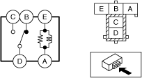
Type A
1. Remove the relay. (See RELAY LOCATION.)
2. Verify the continuity between relay terminals C and D.
am6zzw00009104
|
3. Verify the continuity between relay terminals E and A.
4. Apply battery voltage to relay terminal E, and connect terminal A to ground.
5. Verify the continuity between relay terminals C and D.
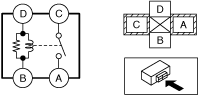
Type B
1. Remove the relay. (See RELAY LOCATION.)
2. Verify the continuity between relay terminals C and D.
adejjw00009219
|
3. Verify the continuity between the relay terminals E and A.
4. Verify the continuity between the relay terminals B and D.
5. Apply battery voltage to relay terminal E, and connect terminal A to ground.
6. Verify the continuity between relay terminals C and D.
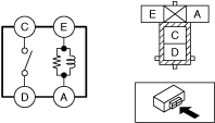
Type C
1. Remove the relay. (See RELAY LOCATION.)
2. Verify the continuity between the relay terminals C and A.
adejjw00009220
|
3. Verify the continuity between the relay terminals D and B.
4. Apply battery voltage to relay terminal D, and connect terminal B to ground.
5. Verify the continuity between relay terminals C and A.