 |
ac5ccw00001367
GENERATOR REMOVAL/INSTALLATION [WITH i-ELOOP (SKYACTIV-G 2.5 (WITH CYLINDER DEACTIVATION))]
id1317040030r5
Procedure Before i-ELOOP-Related Part Servicing
Generator Removal/Installation
1. Disconnect the negative battery terminal. (See NEGATIVE BATTERY TERMINAL DISCONNECTION/CONNECTION.)
2. Remove the plug hole plate. (See PLUG HOLE PLATE REMOVAL/INSTALLATION [WITH CYLINDER DEACTIVATION (SKYACTIV-G 2.0, SKYACTIV-G 2.5)].)
3. Remove the front splash shield (RH). (See SPLASH SHIELD REMOVAL/INSTALLATION.)
4. Remove the front under cover No.2. (See FRONT UNDER COVER No.2 REMOVAL/INSTALLATION.)
5. Remove the generator drive belt. (See DRIVE BELT REMOVAL/INSTALLATION [WITH CYLINDER DEACTIVATION (SKYACTIV-G 2.0, SKYACTIV-G 2.5)].)
6. Remove the drive belt auto tensioner. (See DRIVE BELT AUTO TENSIONER REMOVAL/INSTALLATION [WITH CYLINDER DEACTIVATION (SKYACTIV-G 2.0, SKYACTIV-G 2.5)].)
7. Remove the A/C compressor with the cooler hose still connected and secure it using wire or rope so that it is out of the way. (See A/C COMPRESSOR REMOVAL/INSTALLATION [SKYACTIV-G 2.0, SKYACTIV-G 2.5].)
8. Disconnect the service plug. (See SERVICE PLUG DISCONNECTION/CONNECTION [i-ELOOP].)
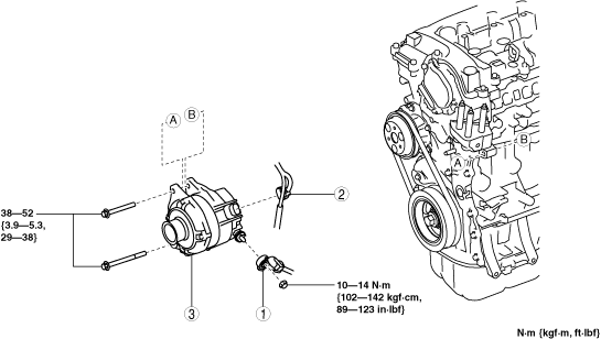
9. Remove in the order indicated in the table.
10. Install in the reverse order of removal.
ac5ccw00001367
|
|
1
|
Terminal B cable
|
|
2
|
Generator connector
|
|
3
|
Generator
(See Generator removal note.)
(See Generator installation note.)
|
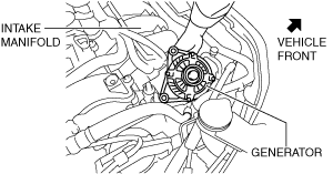
Generator removal note
1. Fully loosen the generator lower bolt and pull it outward until it contacts the body frame.
2. Remove the generator upper bolt.
3. Remove the generator together with the lower bolt from the engine.
4. Remove the generator from above the engine compartment.
ac5wzw00010884
|
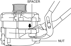
Generator installation note
1. To facilitate the installation of the generator to the engine, grasp the spacer in the bolt installation hole using pliers and push it down to the nut side.
ac5wzw00002650
|
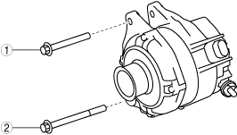
2. Insert the generator lower bolt into the generator.
3. Align the bolt installation holes on the engine and generator sides and temporarily tighten the generator upper bolt and generator lower bolt.
4. Tighten the bolts in the order shown in the figure.
ac5jjw00010651
|